Project 1 (Mini Project on Vehicle Direction Detection
Mini Project - Vehicle Direction Determination
Solution:
The objective of the project was to develop of MATLAB Simulink model as per the requirement shown below:
REQ 1:
- Steering wheel input as yaw rate (Signal name: SteeringWheel_YawDegreeInput) is the input for this system.
- This is compared against three angular values, each for a left turn, right turn & straight drive (CalibrationValues: Right_Turn_AngularLimit, Left_Turn_AngularLimit, Straight_Drive_Steering_Angle) to say which specific direction the steering wheel is turning towards.
- Use switch blocks to compare & develop this requirement. Keep this requirement in a subsystem & the output of this requirement is a local signal (Signal Name: Vehicle_Turn_Status).
REQ 2:
- Inputs to this requirement are a local signal from requirement 1 (Signal Name: Vehicle_Turn_Status) & an input signal from the camera (Signal Name: CameraInput_RoadSign) that confirms the occurrence of a road sign.
- Signal Vehicle_Turn_Status is compared against calibration values (Calibration Values: RightTurn_RoadSign, LeftTurn_RoadSign, Straight_RoadSign), if each of them is found equal, then each of the three corresponding output is compared against the camera input signal,
- Using a logical operator block, only one among them is finally given as output signal (Signal Name: Vehicle_Direction_Indicator).
The Simulink model for the above requirement is shown below:
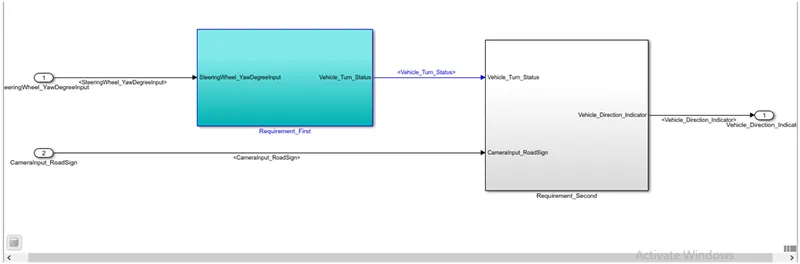
Simulink design based on requirement 1:
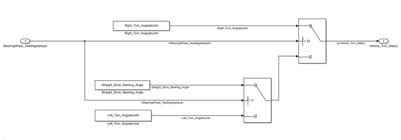
The simulation for requirement 1 uses three constant and switch blocks.
An input signal straightwheel_yawChangeinput is given to a switch block which compares it from the correct turn angle value. A threshold value of switch one is set as 25 since the initial value assigned to the right turn angle limit is 30. Whereas switch 2 compares straight drive angle and left turn angle, the output of the switch is given to switch 1. The result of switch 1 provides the vehicle with turn status.
Simulink design based on requirement 2:
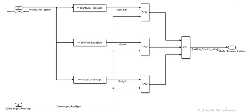
As per requirement 2, the output of requirement 1, vehicle turn status, is input for requirement 2. A camera read sign is provided as a second input to requirement 2. The vehicle turn status is compared to road signs, i.e., right, left, and straight.
The road sign right, left, and straight is given to a comparable stable block the output of this block Boolean. The camera input which reads the road sign is also a Boolean input. The production of compared constant block and camera input is given an AND logic block. If both information and logic are accurate, then the output will be actual. Else, the case output is false. The result of AND reason is given OR sense to get production. OR gate will provide accurate work if any input is valid.
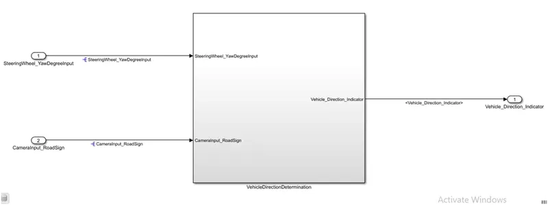
A complete vehicle direction determination Simulink.
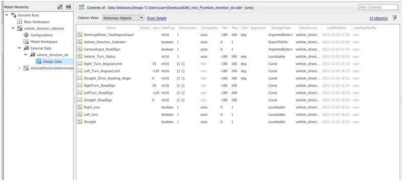
An SLDD file is also created and linked to the vehicle direction determination Simulink model.
The SLDD file has two input signals: one output signal, six calibrated parameters, and three local signals.
The SLDD file is shown below:
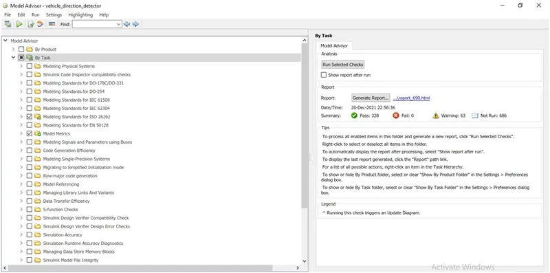
A Model Advisor report for the same is generated, shown below. The information generated shows no failure. Report is generated of ISO26262, MAAB guideline and MISRA. The report shows 63 warning.
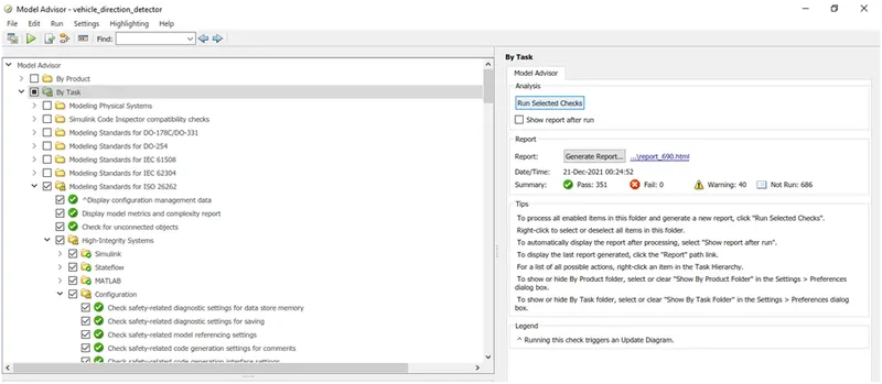
After going through the some warning were addressed and further warning were reduced to 40 shown below:
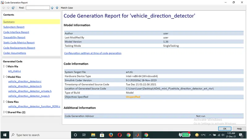
The code generated for the model and model works perfectly. Before the Model advisor and code generation some configuration parameters of model is change and Embedded coder is get code. Code generation report is shown below:
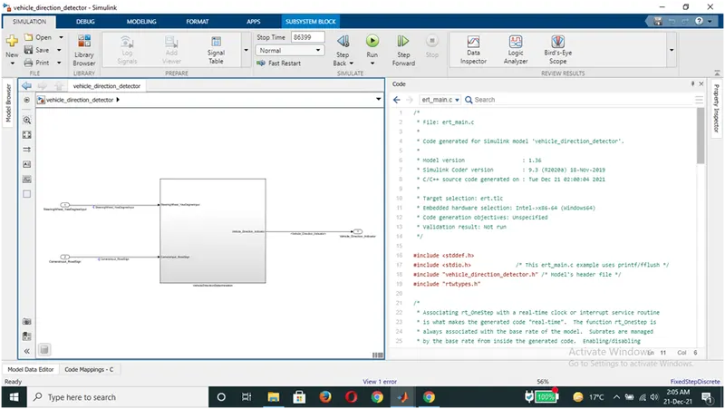
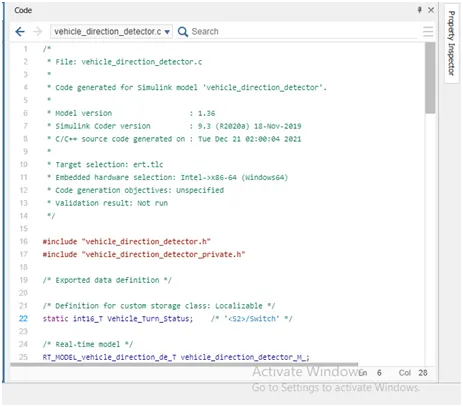
/*
 * File: vehicle_direction_detector.c
 *
 * Code generated for Simulink model 'vehicle_direction_detector'.
 *
 * Model version                  : 1.36
 * Simulink Coder version         : 9.3 (R2020a) 18-Nov-2019
 * C/C++ source code generated on : Tue Dec 21 02:00:04 2021
 *
 * Target selection: ert.tlc
 * Embedded hardware selection: Intel->x86-64 (Windows64)
 * Code generation objectives: Unspecified
 * Validation result: Not run
 */

#include "vehicle_direction_detector.h"
#include "vehicle_direction_detector_private.h"

/* Exported data definition */

/* Definition for custom storage class: Localizable */
static int16_T Vehicle_Turn_Status;    /* '<S2>/Switch' */

/* Real-time model */
RT_MODEL_vehicle_direction_de_T vehicle_direction_detector_M_;
RT_MODEL_vehicle_direction_de_T *const vehicle_direction_detector_M =
  &vehicle_direction_detector_M_;
static void rate_scheduler(void);

/*
 *   This function updates active task flag for each subrate.
 * The function is called at model base rate, hence the
 * generated code self-manages all its subrates.
 */
static void rate_scheduler(void)
{
  /* Compute which subrates run during the next base time step.  Subrates
   * are an integer multiple of the base rate counter.  Therefore, the subtask
   * counter is reset when it reaches its limit (zero means run).
   */
  (vehicle_direction_detector_M->Timing.TaskCounters.TID[1])++;
  if ((vehicle_direction_detector_M->Timing.TaskCounters.TID[1]) > 999) {/* Sample time: [0.01s, 0.0s] */
    vehicle_direction_detector_M->Timing.TaskCounters.TID[1] = 0;
  }
}

/* Model step function */
void vehicle_direction_detector_step(void)
{
  if (vehicle_direction_detector_M->Timing.TaskCounters.TID[1] == 0) {
    /* Switch: '<S2>/Switch' incorporates:
     *  Constant: '<S2>/Left_Turn_AngularLimit'
     *  Constant: '<S2>/Right_Turn_AngularLimit'
     *  Inport: '<Root>/SteeringWheel_YawDegreeInput'
     *  Switch: '<S2>/Switch1'
     */
    if (SteeringWheel_YawDegreeInput > 25) {
      Vehicle_Turn_Status = Right_Turn_AngularLimit;
    } else if (SteeringWheel_YawDegreeInput > 0) {
      /* Switch: '<S2>/Switch1' incorporates:
       *  Constant: '<S2>/Straight_Drive_Steering_Angle'
       */
      Vehicle_Turn_Status = Straight_Drive_Steering_Angle;
    } else {
      Vehicle_Turn_Status = Left_Turn_AngularLimit;
    }

    /* End of Switch: '<S2>/Switch' */

    /* Logic: '<S3>/OR' incorporates:
     *  Constant: '<S4>/Constant'
     *  Constant: '<S5>/Constant'
     *  Constant: '<S6>/Constant'
     *  Inport: '<Root>/CameraInput_RoadSign'
     *  Logic: '<S3>/AND'
     *  Logic: '<S3>/AND1'
     *  Logic: '<S3>/AND2'
     *  RelationalOperator: '<S4>/Compare'
     *  RelationalOperator: '<S5>/Compare'
     *  RelationalOperator: '<S6>/Compare'
     */
    Vehicle_Direction_Indicator = ((((Vehicle_Turn_Status == RightTurn_RoadSign)
      && CameraInput_RoadSign) || ((Vehicle_Turn_Status == LeftTurn_RoadSign) &&
      CameraInput_RoadSign)) || ((Vehicle_Turn_Status == Straight_RoadSign) &&
      CameraInput_RoadSign));
  }

  rate_scheduler();
}

/* Model initialize function */
void vehicle_direction_detector_initialize(void)
{
  /* Registration code */

  /* initialize real-time model */
  (void) memset((void *)vehicle_direction_detector_M, 0,
                sizeof(RT_MODEL_vehicle_direction_de_T));

  /* block I/O */

  /* custom signals */
  Vehicle_Turn_Status = 0;
  Vehicle_Direction_Indicator = false;
}

/*
 * File trailer for generated code.
 *
 * [EOF]
 */
Conclusion: The simulation to design an MBD model for vehicle direction determination is done. The model advisor report for the same is generated, and code for the same is also generated.