Project 1 (Mini Project on Vehicle Direction Detection
Project 1: Mini Project on Vehicle Direction Detection
-
Objectives of the Project:
- To develop the MATLAB Simulink model as per the given requirement.
- To tag the requirements to the Simulink model.
- To choose code generation,
- Storage class for Input signals: ImportedExtern
- Storage class for Output signal: Export to File
- Storage class for local signals: localizable
- Storage class calibration signals: Const.
- To choose sample time for all signals as 0.01s
Requirement - 1:
- Steering wheel input as yaw rate (Signal name: SteeringWheel_YawDegreeInput) is the input for this system.
- This is compared against 3 angular values, one each for a left turn, right turn & straight drive (Calibration Values: Right_Turn_AngularLimit, Left_Turn_AngularLimit, Straight_Drive_Steering_Angle) to say which specific direction the steering wheel is turning towards.
- Use switch blocks to compare & develop this requirement. Keep this requirement in a subsystem & the output of this requirement is a local signal (Signal Name: Vehicle_Turn_Status).
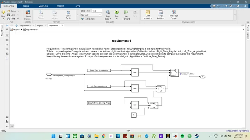
Here, in the requirement 1 subsystem,
the Steering wheel input is given as yaw rate with the Signal name: SteeringWheel_YawDegreeInput which is the input for this system.
And this signal is compared against 3 angular values, one each for a left turn, right turn & straight drive assigned as the Calibration Values, like Right_Turn_AngularLimit, Left_Turn_AngularLimit, and Straight_Drive_Steering_Angle to compare with the input yaw rate of the steering wheel.
Also, multiple switch blocks and Compare blocks are used to compare & develop this requirement.
The output of this requirement is a local signal with the resolved Signal Name: Vehicle_Turn_Status.
Requirement – 2:
- Keep this requirement as a separate subsystem. Inputs to this requirement are a local signal from requirement 1 (Signal Name: Vehicle_Turn_Status) & an input signal from the camera (Signal Name: CameraInput_RoadSign), which confirms the occurrence of a road sign.
- Signal Vehicle_Turn_Status is compared against calibration values (Calibration Values: RightTurn_RoadSign, LeftTurn_RoadSign, Straight_RoadSign), if each of them is found equal, then each of the three corresponding output is compared against the camera input signal,
- Using a logical operator block, only one among them is finally given as output signal (Signal Name: Vehicle_Direction_Indicator).
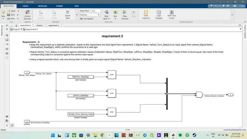
In the Requirement 2 subsystem,
The Inputs to this requirement are local signals from requirement 1 with Signal Name: Vehicle_Turn_Status & an input signal of the camera sensor from the camera Signal Name: CameraInput_RoadSign, which confirms the occurrence of a road sign.
Here, the Signal Vehicle_Turn_Status is compared against calibration values with the Calibration Values of RightTurn_RoadSign, LeftTurn_RoadSigna, and Straight_RoadSign.
if any of them is found equal, then each of the three corresponding outputs is compared against the camera input signal. While Using a logical operator block, only one among them is finally given as output signal with the Signal Name: Vehicle_Direction_Indicator.
And this requirement is kept as a separate subsystem.
Simulink Data Dictionary: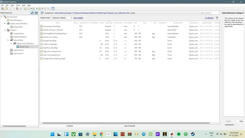
The given parameters are defined as the sldd file along with its Storage class and Datatypes.
for Input signals, the storage class is chosen as ImportedExternwhile for the Storage class for the Output signal, Export to File is used. In the case of the Storage class for local signals, localizable is preferred, and in the case of the Storage class for calibration signals, Const is used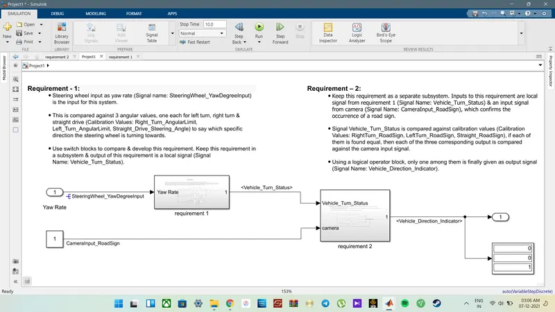
- Procedure:
- Steering wheel input is defined as yaw rate with the Signal name, SteeringWheel_YawDegreeInput, and is the input for this system.
- This input for the system is compared against 3 angular values, one each for a left turn, right turn & straight drive which are defined as Calibration Values of Right_Turn_AngularLimit, Left_Turn_AngularLimit, and Straight_Drive_Steering_Angle, which is to say which specific direction the steering wheel is turning towards.
- We can Use switch blocks, relational and logical operators to compare & develop this requirement. This system, labeled as Requirement 1 keeps this requirement in a subsystem & the output of this requirement is directed to a local signal and is denoted with the Signal Name: Vehicle_Turn_Status.
- Steering wheel input is defined as yaw rate with the Signal name, SteeringWheel_YawDegreeInput, and is the input for this system.
- Observation:
- When the Yaw Rate input is 30 degrees, the steering turns right, else
- if it is -120 degrees, the steering is rotated left or,
- the vehicle continues to go straight
- If any of the above-mentioned conditions is true and when the observed output is compared to the camera input
- if any of the conditions matches, the vehicle will behave accordingly.
When input = 30,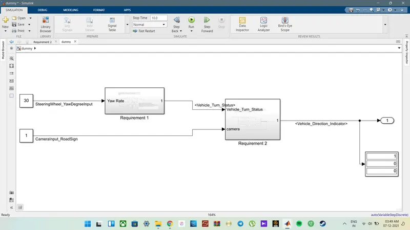
When input = -120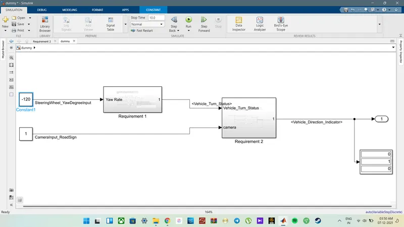
when input = 0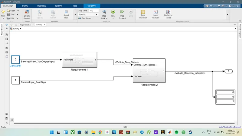
RESULT:
-
Identifying the direction of the vehicle is one of the important & diverse features in Autonomous driving & Advanced Driver Assistance Features.
- Developed the MATLAB Simulink model as per requirement.
- Analyzed the data information extracted from a camera that reads the road signs & compares it with the specific values for a left turn, right turn & straight drive.
- As following the requirement, the desired outputs were achieved using a simple Simulink block system with the help of some Switch blocks, Relational and Logical operators.