Project 1 (Mini Project on Vehicle Direction Detection
1. Aim :-
Mini Project on Vehicle Direction Detection.
2. Introduction :-
Vehicle direction detection is one of the feature used in autonomous driving and advanced driver assistance system (ADAS).
In this input is taken with help of cameras which detects the roadside traffic signs which is further given to electronic control unit and corresponding commands are generated which will help in direction detection of vehicle.
Vehicle Direction Determination can also be coupled along - side features like GPS systems to identify whether the vehicle is reaching its destination in an optimized manner.
This sub feature can also be used along with Lane Detection, Highway Warning, Ramp Entry / Exit in Wrong Way Detection etc.
Yaw is simply an indication of a vehicle's rotation from it's vertical axis or how far is the vehicle angled to the left or right away from its center or how far has the vehicle deviated from it's straight course.
In this project two inputs are taken one is steering input as yaw rate and other one is camera input . Output is vehicle direction detection status.
During simulink model sone blocks are used which are listed below :-
- Constant
- Relational operator
- Logical operator
- Scope
In this project we linked this model with simulink data dictionary(SLDD) and requirement tagging is also done seperately for each requirement.
3. Workdone :-
Simulink model for this project are made on the basis of requirement which are mentioned below :-
Requirement - 1:
- Steering wheel input as yaw rate (Signal name: SteeringWheel_YawDegreeInput) is the input for this system.
- This is compared against 3 angular values, one each for left turn, right turn & straight drive (Calibration Values: Right_Turn_AngularLimit, Left_Turn_AngularLimit, Straight_Drive_Steering_Angle) to say which specific direction the steering wheel is turning towards.
- Use switch blocks to compare & develop this requirement. Keep this requirement in a subsystem & output of this requirement is a local signal (Signal Name: Vehicle_Turn_Status).
Requirement – 2:
- Keep this requirement as a separate subsystem. Inputs to this requirement are local signal from requirement 1 (Signal Name: Vehicle_Turn_Status) & an input signal from camera (Signal Name: CameraInput_RoadSign), which confirms the occurrence of a road sign.
- Signal Vehicle_Turn_Status is compared against calibration values (Calibration Values: RightTurn_RoadSign, LeftTurn_RoadSign, Straight_RoadSign), if each of them is found equal, then each of the three corresponding output is compared against the camera input signal,
- Using a logical operator block, only one among them is finally given as output signal (Signal Name: Vehicle_Direction_Indicator).
The matlab model is as follows :-
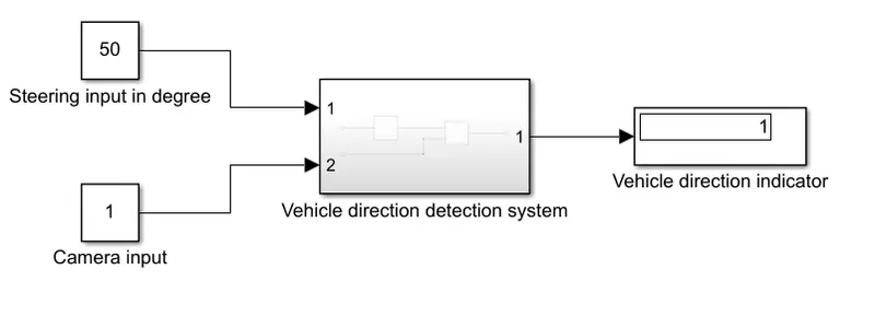
This is the vehicle direction detection subsystem inside this logic building is done . It has two input as steering input (in degree) and camera input and result is seen at scope.
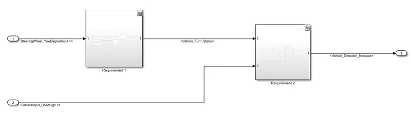
In this again two subsytem are present as requirement 1 and requirement 2.
The model inside requirement 1 subsytem is :-
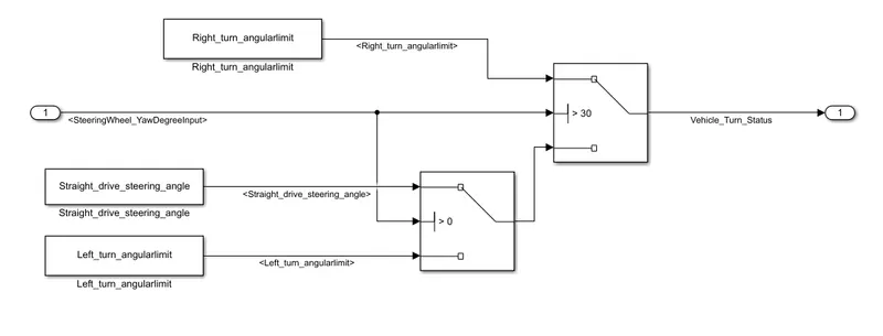
Here steering wheel input is compared with right turn limit ,left turn limit and straight limit and further given to switches.
As for example in this project , right turn angular limit is set as 30 degree ,left turn limit is set as -120 degree and staright drive steering angle as 0 degree.
Two switches are used and there threshold are set as ,for switch 1 threshold isright turn angular limit for switch two threshold is straight drive steering angle.
If input is more than right turn angle limit then then vehicle status is right turn else it is compared with second threshold as straight drive steering angle so vehicle status as straight drive.
The model inside requirement 1 subsytem is :-
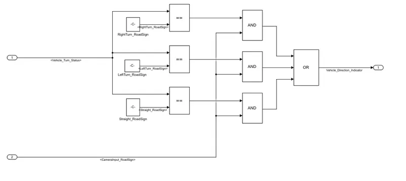
In this two input as vehicle status in degree and camera input in boolean (0 or 1) , here vehicle status is compared with right ,left and straight road sign and given to relational operator if both are each then it produces 1 else 0.
Then finally compared with and gate and given to OR gate .OR gate produces 1 even if one ipnut is 1 .
Simulink data dictionary (SLDD) is made and linked to matlab model which is as shown :-
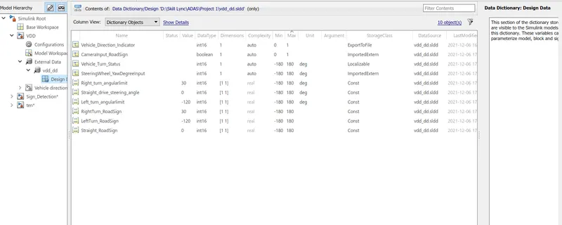
In the sldd all signals input,output and local signals and constant parameter are defined in full details like its minimum and maximum value ,its datatype its intial value ,etc.
Requirement tagging is also done seperately for each subsytem,whose files are attached.
4. Result :-
Consider an steering inpiut as 50 degree , which is more than right turn angular limit so vehicle turn status is right turn.
As this right turn status of 50 degree is compared with road rifht,left and staright sign .If they found equal it genrate logical 1.
If this 1 is equal to camera input as 1 there anding is 1 and given to OR gate .
At that time other input to OR gate is 0,so out of three two input is 0 and one is 1 and therefore result is 1.
It means vehicle direction indictor shows right turn which is defined in scope as 1.
5. Conclusion :-
Comprehensive simulation has been carried out in MATLAB/SIMULINK and project is throughly analysed .