Project 1 (Mini Project on Vehicle Direction Detection
Answer:
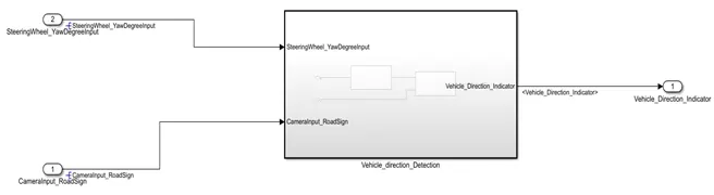
Fig_1: Vehicle_direction_Detection Subsystem
The vehicle_direction_detection subsystem is made as per the question requirements.
It has two inputs “SteeringWheel_YawDegreeInput” and “CameraInput_RoadSign” , also it has one output for “Vehicle_direction_detection”
This subsystem is further divided into two subsystems for Requirement-1 and Requirement-2.
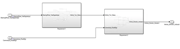
Fig_2: Requirement 1 and Requirement 2 subsystems
Requirement-1:
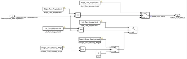
Fig_3: Requirement 1 subsystem
As per the requirement 1 the SteeringWheel_YawDegreeInput is compared with three angular values which are Right_Turn_AngularLimit, Left_Turn_AngularLimit and Straight_Turn_AngularLimit.
If the one of the comparison became true, that compared value will become output. This logic is implemented using nested if…else condition.
Requirement-2:
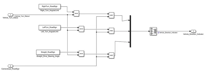
Fig_4: Requirement 2 subsystem
As per the requirement the Vehicle_Turn_Status is compared with three road sign value: RightTurn_RoadSign,LeftTurn_RoadSign and Straight_RoadSign. That each of the output is compared with CameraInput_RoadSign. And the output of that is Vehicle_Direction_Indicator.
Requirement Tagging:
Requirement tagging is the facility provided by the MATLAB, which is used to tag sub system which is made according to the customer requirement.
Hence if the requirement tagging is done, it is easier to read the demanded requirement by the customer at any time in the Simulink model.
There is no need to open again separate file for that, it is time saving option.
Steps for requirement tagging:
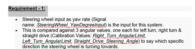
Select a word for respective requirement.
Then go to MATLAB Simulink subsystem for which the requirement tagging is needed.
Select the subsystem and select requirement and then select Link to selection in word.
Hence it will tag the subsystem with the section.
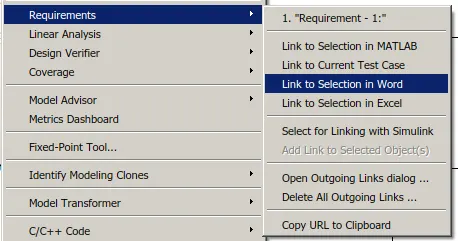
Here the selection is already done that’s why it showing requirement 1 on the top of the option.
Simulink Data directory (SLDD):
SLDD is the declaration of the variable in the simulation model apart from only initializing value is script and workspace it adds more details about the variables.
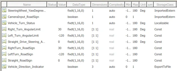
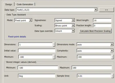
The above SLDD is made in the Simulink model as per given in the question. Also the sample time for all the signal is taken as 0.01sec.
Here fixdt(1,16,0) represent signed 16 data type and fixdt(0,16,0) for unsigned.
Model advisor test (MAB testing):
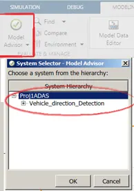
To do the model advisor test first go to modeling and click on model advisor menu. Then select the system for which the test is going to perform.
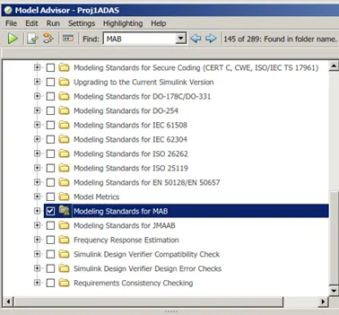
Now select MAB for doing MATLAB advisory board test for the system, then click on the ren checks.
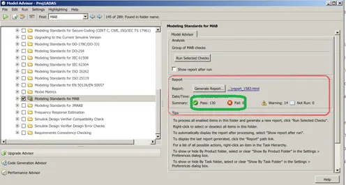
In the model advisory test, it should show all the checks pass and none fail, so that the model is perfect for code generation.
Creating MIL and SIL test Harness Templet Only:
MIL test templet:
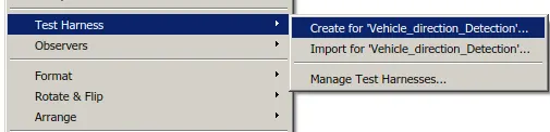
For creating the test harness for the subsystem the system chosen should be checked on treat as atomic subsystem in block property.
Then right click on the system and click on the Test Harness-à then create for ‘Name of subsystem.
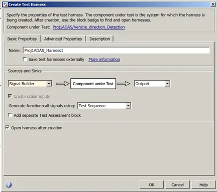
Then choose source as signal builder and sink is outport. Then click on OK.
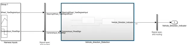
Then new file window will popups and it is nothing but MIL test harness template.
This is the process to creating MIL test templet only. Here test is not performed by importing the signal into signal building block and testing the system.
SIL test Templet:
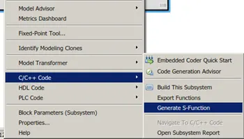
For creating SIL templet right click on the system and select C/C++ code and then click on the Generate S- Function.
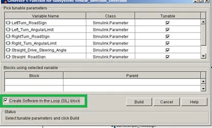
Then new dialog box will popups, where we need to select the create Software-in-Loop(SIL) block.
Then click on Build.
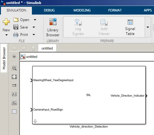
Then new window will popup, in which the SIL is created and which is nothing but and transformation of the blocks present in the previous system into the code.
That block is can be again used for the testing for the model.
List of files
| Proj1ADAS.docx -- Include Requirement tagging |
| Proj1ADAS.slx -- simulink Model |
| SILProj1ADAS.slx -- SIL Templete of model |
| ProjM_w3_mini.sldd -- Simulink Data Directory File |
Requirement - 1:
- Steering wheel input as yaw rate (Signal name: SteeringWheel_YawDegreeInput) is the input for this system.
- This is compared against 3 angular values, one each for left turn, right turn & straight drive (Calibration Values: Right_Turn_AngularLimit, Left_Turn_AngularLimit, Straight_Drive_Steering_Angle) to say which specific direction the steering wheel is turning towards.
- Use switch blocks to compare & develop this requirement. Keep this requirement in a subsystem & output of this requirement is a local signal (Signal Name: Vehicle_Turn_Status).
Requirement – 2:
- Keep this requirement as a separate subsystem. Inputs to this requirement are local signal from requirement 1 (Signal Name: Vehicle_Turn_Status) & an input signal from camera (Signal Name: CameraInput_RoadSign), which confirms the occurrence of a road sign.
- Signal Vehicle_Turn_Status is compared against calibration values (Calibration Values: RightTurn_RoadSign, LeftTurn_RoadSign, Straight_RoadSign), if each of them is found equal, then each of the three corresponding output is compared against the camera input signal,
- Using a logical operator block, only one among them is finally given as output signal (Signal Name: Vehicle_Direction_Indicator).