Project 1 - Meshing of Floor Panel
Objective
generate mid surface and geometry clean up.
generate mesh with low tria concentration and proper mesh flow.
model should pass all the given quality parametets.
Cad model image
Procedure with required images
1. import the cad model (igs) in the ANSA software.\
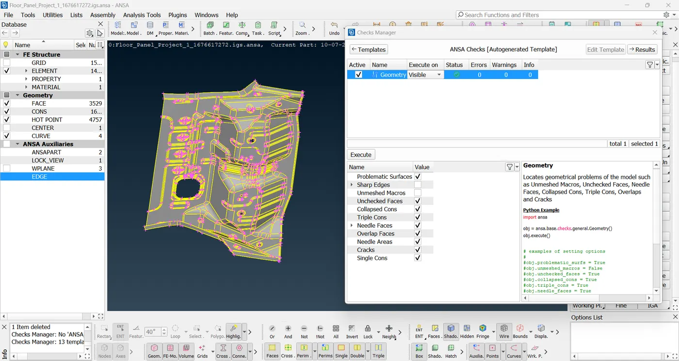
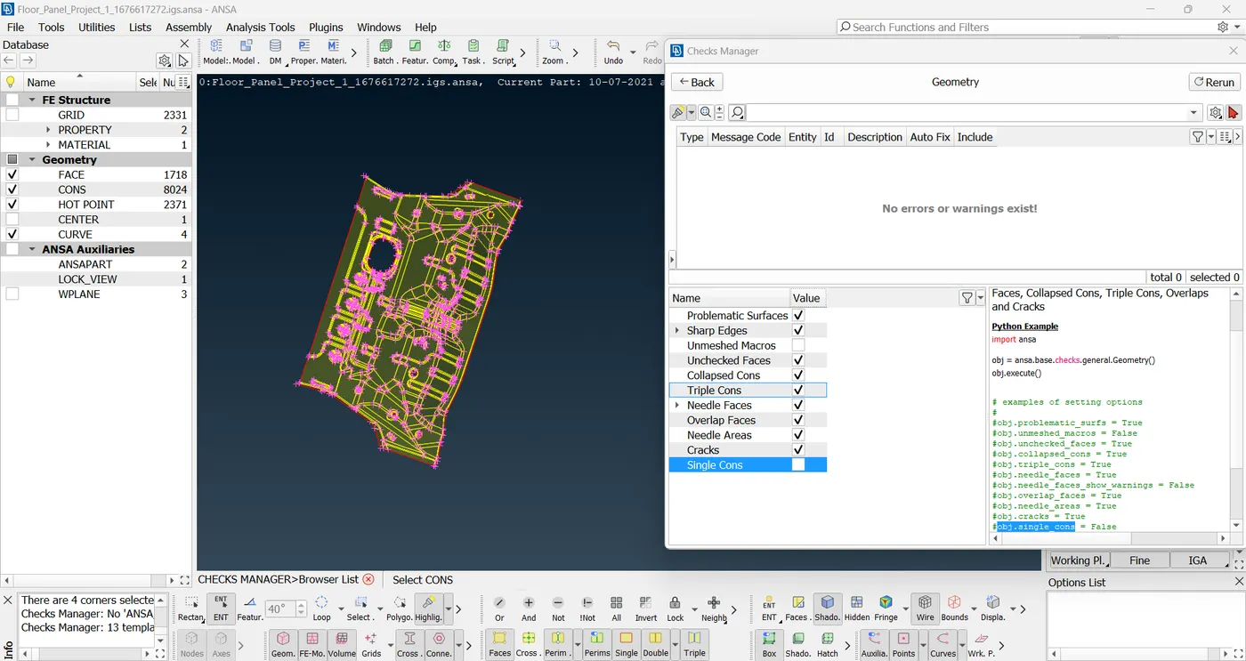
2. go to checks->geometry to see all the geometry errors in the input cad file. we need to resolve these.
3. go to topo module for this. use hot points insert, delete, release to manipulate points data. use cons release to manipulate the edges. use faces cut, new, delete, topo, project cut, mid-surface skin, plane cut, orient to do operations related to plane. use curves create to make a new curve. use auxiliaries fine to see finer details in the shape of sheet you want to modify. use all these commands to solve the geometry errors and reduce them to zero.
4. now we need to generate the mid-surface. the input CAD has many curved surfaces. further we need a closed volume to take a mid-surface. use mid-surface-skin command to generate the mid-surface in this case because it is the best way to do it for these kind of surfaces where every surface has a curve. the mid-surface method allows you to assign the actual physical thickness of the part as a property. also manually going for a mid-surface would mean you have to offset each every small part by a value which will make it inefficient in terms of time. plus you may have to use topo again after all the offsets are done. using this command speeds up the process of taking a mid-surface by combining the above two actions into one and makes the user's job easy. offset the value as required. here, the thickness of the CAD model was 1 mm. so the offset distance was 0.5 mm. now we have a successfully generated mid-surface.
5. now go to the mesh module - classic mesh. we are going to mesh on this mid-surface generated.
6. use hot points insert, delete to manipulate the points. firstly, use perimeters-length to select the whole surface and input 5 mm as value in perimeter. this will set the perimeter points to roughly 5 mm distance apart. we do this since the target element length in challenge is specified as 5 mm.
7. do the same with macro now.
8. now use macros cut to cut different portions on the mid-surface to have a better flowing mesh. then after meshing is done use macros-join to join all the separated surfaces since we need the original surface as a whole mesh.
9. for the circles looking as hexagons or squares on the screen, we need to align their one side parallel to the perimeter side. this helps in better meshing. use perimeters-slide option to do so.
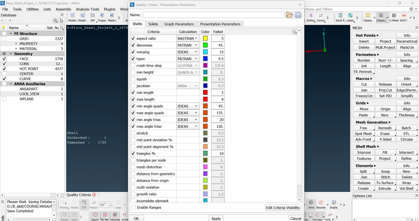
10. now set the following quality criteria. go to quality and fill in the following quality criteria. click apply.
| S.N | Quality Criteria | Value |
| 1 | Aspect Ratio | 5 |
| 2 | Skewness | 45 |
| 3 | Warping | 15 |
| 4 | Taper | 0.5 |
| 5 | Min. Length | 2 Units |
| 6 | Max. Length | 8 Units |
| 7 | Min angle Quad | 45 |
| 8 | Max angle Quad | 135 |
| 9 | Min angle Tria | 20 |
| 10 | Max angle Tria | 120 |
| 10 | Tria % | 10 |
11. now we are ready to mesh the surface. use mesh generation - best mesh to have a mesh to start with. use shell mesh-reshape to select the areas where quality criteria are failing. use reconstruct to reconstruct a portion of mesh. use macro area option to select only a region of surface before meshing.
12. in the generated mesh, the triangles% is less, according to the challenge requirement.
Completed Model and Final model image
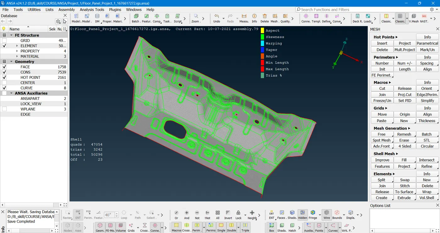
the above model passes all the quality parameters!
all the necessary and required files can be found here
link to required files - https://drive.google.com/drive/folders/1KuHUpj6CiydIQ4koWzeVazbLYdcZm8lr?usp=sharing