Project 1 - Meshing of Floor Panel
OBECTIVE
The objective of this assignment is to mesh the given CAD model with a target element length of 5 following the given quality criteria.
|
Sl no |
Quality criteria | Value |
| 1 | Target /average length | 5 |
| 2 | Minimum length | 2 |
| 3 | Maximum length | 8 |
| 4 | Aspect | 5 |
| 5 | Warpage | 15 |
| 6 | Skewness | 45 |
| 7 | Minimum quad angle | 45 |
| 8 | Maximum quad angle | 135 |
| 9 | Minimum tria angle | 20 |
| 10 | Maximum tria angle | 120 |
| 11 | Tria percentage | 10 |
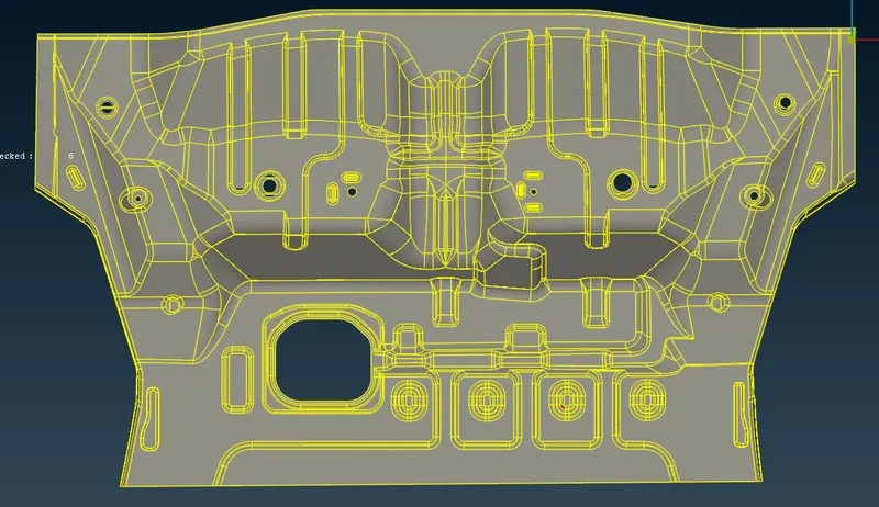
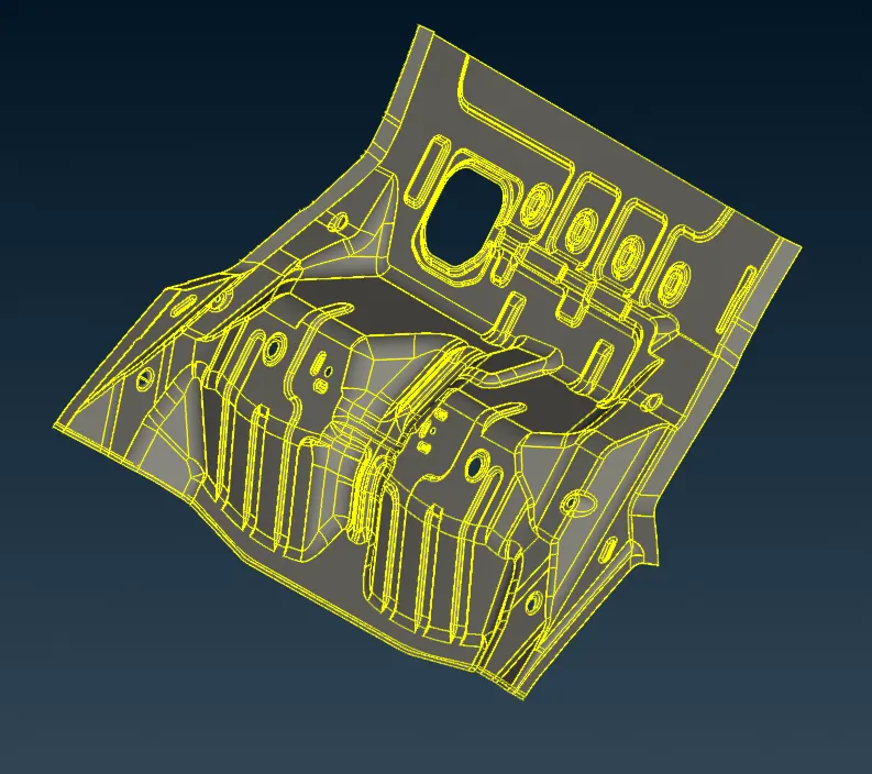
The cad model image of the given assembly is shown below.
PROCEDURE
The model is imported onto ansa and then topology operation is performed. Then it is checked for any geometry errors using the checks>geometry tool. Some geometry errors can easily be fixed using checks>geometry>fix option. More complex geometry errors were fixed using tools such as faces>delete , faces> new>fitted , faces>modify, cons>release etc. Here we go for automidsurface (midsurface>skin) option since it was giving a clean midsurface. While generating automidsurface ,thickness can be applied to it automactically by selecting the "apply estimated thickness" options from the options list. After cleanup the part is meshed from one side.
The mesh parameters and mesh quality criteria is then assigned. Since our target element length is 5 , shell element length is set to 5 using length option (mesh>perimeters>length). Unwanted feature lines are suppresed using join (mesh>macros>join) tool. The component is then meshed part by part using mesh generation>best tool. The generated mesh may not always be good in quality so to improve quality shellmesh>reconstruct option is used when needed. Some of the common criterias that were followed to obtain a geat quality mesh were
- The tria elements should never be opposite to each other
- No tria elements should be connected back to back
- No tria elements should be on the edge of the geometry
- No tria elements should be on the edge of the geometry
- No tria elements should be near the holes.
- No tria elements should be on the feature and the fillets
- There should be less tria concentration.
Most quality issues relating to tria were managed using elements>split, elements>swap, elements>join, grids>paste ,shell mesh>smooth options.Warpage issues were common occourence in areas where there was a sharp turn in geometry, these were fixed by using grids>move tool . Sometimes shell mesh>smooth tool also worked.Some other tools which were used during meshing were macros>edge to perimeter, grids>origin ,mesh generation>erase, macros>cut etc.. Some areas of the geometry had symmetic faces but was not exactly symmetrical about a plane. So in this case , faces that had plane symmetry were first reflected about their plane of symmetry and then was attached to the desired position using transform>move>transform option.
RESULTS
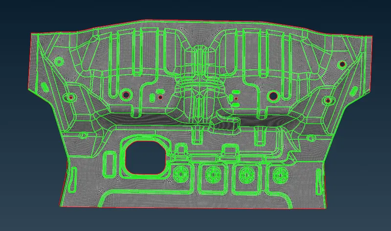
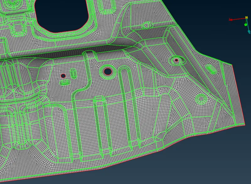
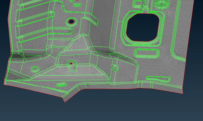
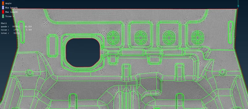
The component was successfully meshed satisfying all the quality criterias .The final meshed model is shown below.