Project 1 Mechanical design of battery pack
Aim :
Battery pack capacity: 18 kWh, Cell: ANR26650M1-B. Prepare a detailed battery pack drawing along with its enclosure. State your assumptions.
Introduction :
- Lithium ion cells are capable of delivering very high power. Lithium ion cells are used in aerospace, automotive electric vehicles, mobiles, medical devices and other electronic devices. The battery pack of a electric vehicle generally consists of series or parallel connections. Large battery packs have multiple cell modules in which many cells are kept together to build a large battery pack. A series connection is used to compound the voltage where the parallel connection is for compund current capacity.
- A battery cell consists of five major components that are electrodes, anode, cathode, separators, terminals, electrolyte and enclosure. One of the fundamental components of an electric powertrain is the battery pack. The battery pack is the energy source of the vehicle. The Automotive environment is challenging for batteries are subject to a wide range of operating conditions.
- Thermal consideration are critical to the safety and performance of battery packs, a challenge that is intensified in the cars because of the increased heat generation in batteries at high charge and discharge rates, which are necessary for high power output. Mechanical robustness is also critical challenge, the battery pack must not only be able to withstand vibration and loads from normal driving conditions and acceleration and deceleration, but also maintain structural integrity in crash scenarios.
- This is important for the safety because of impacting lithium ion batteries can be extremely dangerous and cause catastropic failure of the entire battery pack. A battery pack is a set of any number of identical batteries or individual battery cells.
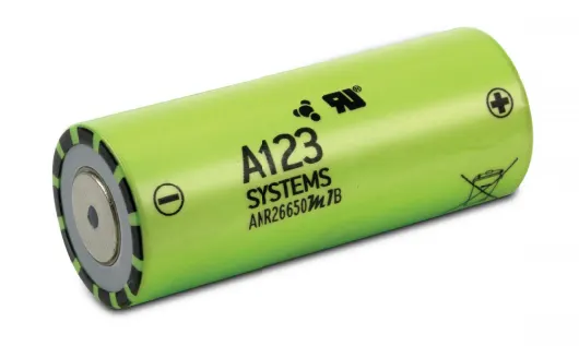
Here an 18 kWh battery pack of model ANR26650M1-B lithium ion cell is used. ANR26650M1-B cell consists of lithium ion phosphate (LiFePO4) and it is best for use in a wide range of temperature and conditions. The ANR26650M1-B lithium ion cell may achieve the following :
- Stable chemistry.
- Faster charging.
- Consistent output.
- Excellent cycle life.
- Superior cost performance.
Common terms used in battery :
- Voltage : Total voltage or voltage of individual cells, minimum and maximum cell voltage or voltage of periodic taps. To maximize the batteries capacity and to prevent localized undercharging and overcharging, the BMS may actively ensure that all the cells that compose the battery are kept at the same voltage or the state of charge, through balancing.
- Tempertaure : Average temperature, coolant intake temperature, coolant output temperature or temperature of individual cells.
- State of Charge (SOC) : Depth of charge (DOD) to indicate the charge level of the battery.
- State of health (SOH) : A variously defined measurement of the remaining capacity of the battery as in percentage of the original capacity.
- State of power (SOP) : The amount of power available for a defined time interval given the current power usage, temperature and other conditions.
- Charging-discharging current : Current In or Out of the battery.
Components of the battery pack :
- Cells (different form factors and their types).
- BMS (electronics to manage the battery).
- Connection system (Connector, pigtail, wires).
- Housing (plastic, sheet metal, shrink etc).
Cells :
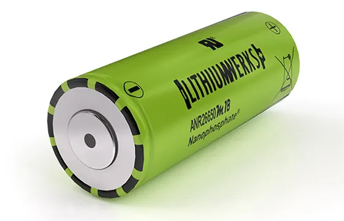
- A pack can contain one cell or many cells configured to achieve higher capacity or output voltage. The cell is considered the fuel tank of the battery pack system in a vehicle. The energy holding that will be released during discharge (when the engine is running) or replaced during a charge cycle (when the tank is refilled at a gas station).
BMS :
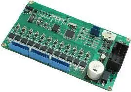
- The BMS is an electronic system that manages a rechargeable battery to ensure it operates safely and efficiently. It is designed to monitor the paramaters associated with the battery packs and their individual cells, applying the collected data to eliminate safety risks and optimise the battery performance.
Connection system :
- The connection system is what transforms a cell into a battery pack. There must be a connection between the cell and the BMS in order to interface with each other. Nickel strips are the preferred method of connecting a battery cell to the control system. A thin strip of nickel is capable of carrying high amounts of current is flexible, durable and can be attached to the cell without the use of excessive heat.
Housing :
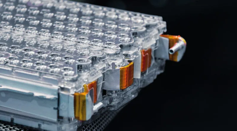
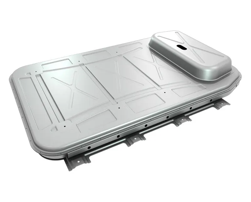
- All of the components that needs to be packaged so that the battery pack can be installed into a device. Once all components are properly placed and connected to one another, they are sealed with either shrink wrap or an hard case. The housing ensures that the components remian safely located and provides a clan package.
Thermal management :
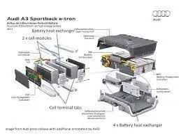
- Thermal management is a major issue in high power designs, particularly for automotive applications. As part of the battery system, it may be necessary to provide air or water cooling ducts, pumps or fans and heat exhangers for high temperature working or heaters for operating in low temperature environments. The layout of the cells should be conductive to manage heat flows within the pack.
Complete battery pack :
Enclosure design :
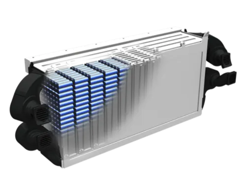
- The energy density improvements of Li-ion cells might be the most prominent battery improvements in the public. There is also an increase in pack level energy density at a greater rate than just cell level improvements.
- Manufacturers are improving their battery designs, the mass of materials being used around the cells is steadily being reduced, allowing for a lighter battery pack or more cells to be used for the same mass.
- The choice of materials for several pack components also affects these improvements. The thermal management strategy also impacts these choices, with increased energy density and consumer demand in fast charging, the thermal management must be more effective but also present in smaller and lighter package,
- Battery pack materials forecasted include aluminium, copper, thermal management materials, steel, glass fibre reinforced polymers, carbon fibre reinforced polymers, inter cell insulation, compression foams and housing and pack fire-retardant materials.
- Enclosured made from injection moulded plastics are commonly used for battery packs. For these enclosed pack designs two or more plastic parts are moulded and then assembled with the pack and accompanying circuitry. They can be sealed using glue, mechanical fasteners or ultrasonic welding. The product cost can be reduced by using insert mouldings in which the interconnection strips and the terminals are moulded into the plastic parts to eliminate both materials and assembly costs.
Datasheet of ANR26650M1-B :
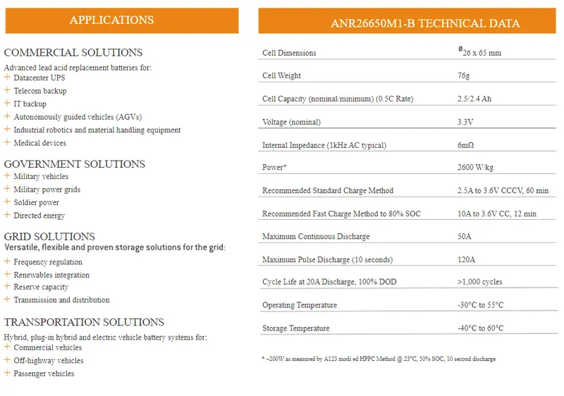
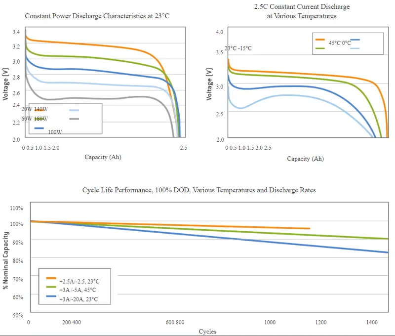
Energy required = 18kWh.
Number of cells (N) = Energy/(nominal voltage*Capacity).
N = 18000/(3.3*2.5)
N = 2182 The minimum cell 2182 is required to get 18kWh energy. When the cells are connected in series the capacity remains the voltage will be the sum of each individual voltage. In parallel connection the voltage remians the same and capacity accumulates.
Nominal voltage of one cell = 3.3V.
Number of cells required to be connected in series connection to produce 330V (Ns) = voltage required/nominal voltage of one cell.
Ns = 330/3.3
Ns = 100. Then 100 cells should be connected in series so that it will generate 330V and the capacity of the module will be 2.5Ah.
To find the number of cells connected in parallel.
Np (cell in parallel) = total cell/Ns.
Np = 2182/100
Np = 21.82
cell architecture = 100S22P where 100 cells in series and 22 cells in parallel.
Battery capacity :
Capacity = parallel cell row*individual cell capacity.
Capacity = 2.5*22
Capacity = 55Ah.
Range :
Powertrain energy consumption = 129 Wh/Km at 70% powertrain efficiency.
Range = capacity/energy consumes per kilometer.
Range = 18000/129.
Range = 139Km.
Battery dimensions :
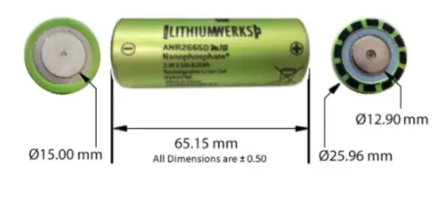
ANR26650M1-B cell has 26mm diameter and 65mm height.
Length of casing (L) = number of cells at mid*(cell diameter(26) + margin at both side of cell (4)) + clearance at side (diameter of edged cell + margin)
L = 98 * 30 + 60
L = 3000mm
Breadth of casing (B) = cell diameter (26) + margin at both side of cell (4) + clearance at side (diameter of edged cell + margin)
B = 20 * 30 + 60
B = 660mm
Height of casing (H) = 65 + 35 (height of cell + margin for, cell holders and metal strips)
H = 100mm.
Weight of battery pack :
Cell weight = 76g.
number of cells = 2182.
Battery pack weight (W) = cell weight * number of cells + weight of accessories.
W = 76 * 2182 + 4.5
= 165.8 + 4.5
= 170.3Kg
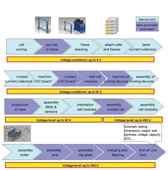
Mechanical design of battery pack :
Conclusion :
A battery pack has been designed using ANR26650M1-B cylindrical cells by calculating several cells, battery voltage and capacity. The required size of the battery pack have also been calculated.
Reference :