Project 1 Mechanical design of battery pack
AIM
To design a battery of 18 kWh by using AN26650M1-B Cell
A123’s high-performance Nanophosphate lithium iron phosphate (LiFePO4) batterytechnology delivers high power and energydensity combined with excellent safety performance and extensive life cycling in alighter weight, more compact package. Our cellshave low capacity loss and impedance growthover time as well as high usable energy over awide state of charge (SOC) range, allowing oursystems to meet end-of-life power and energy requirements with minimal pack oversizing

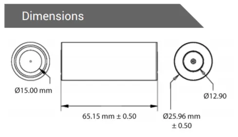
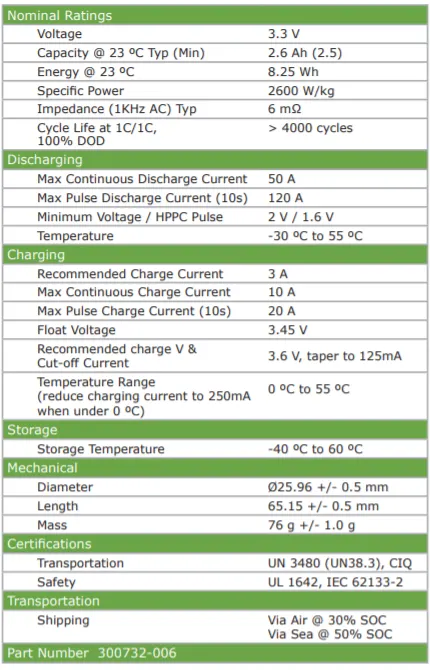
| Cell Dimensions | 26 x 65 mm |
| Cell Weight | 76g |
| Cell Capacity (nominal/minimum) (0.5C Rate) | 2.5/2.4 Ah |
| Voltage (nominal) | 3.3V |
| Internal Impedance (1kHz AC typical) | 6mΩ |
| power | 2600 W/kg |
| Recommended Standard Charge Method | 2.5A to 3.6V CCCV, 60 min |
| Recommended Fast Charge Method to 80% SOC | 10A to 3.6V CC, 12 min |
| Maximum Continuous Discharge | 50A |
| Maximum Pulse Discharge (10 seconds) | 120A |
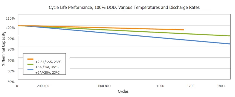
| Cycle Life at 20A Discharge, 100% DOD | >1,000 cycles |
| Operating Temperature | -30°C to 55°C |
| Storage Temperature | -40°C to 60° |
- Lithium Werks’ 26650 cells are capable of delivering very high power due to its use ofpatented Nanophosphate battery technology.
- Based on lithium iron phosphate chemistry(LiFePO4), the cells are inherently safe over a wide range of temperatures and conditions.
- Whether the application requires outstanding cycle life or stable float reliability, the LithiumWerks’ 26650 cells are suitable for a wide variety of power, pulse, or stand-by applications.
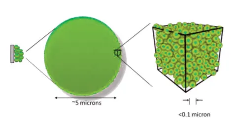
- Nanophosphate® Technology26650 Lithium Ion Power CellNanophosphate battery technology offersstable chemistry, faster charging, consistentoutput, excellent cycle life and superior costperformance.
- It provides the foundation for safesystems whilemeeting the most demanding customer requirements.
- Multiple layers of protection are employed at the chemistry, celland system level to achieve an energy storage solution with superior safety and abuse tolerance compared to metal oxide lithium-ion chemistries.
Features
- The ANR26650M1-B is the next generation of A123 Systems’ pioneering 26650 cylindrical cell, now with greater power and energy density and lower impedance.
- This versatile lithium ion cell is suitable for a wide variety of applications and system designs.
- Proven performance in the toughest conditions, combining durability, reliability, and safety, the ANR26650 cell offers an excellent combination of price-performance.
Cylindrical Cell Primary Applications
- Portable high power devices
- Stationary battery backup systems
- Grid stabilization energy storage systems
- Commercial truck and bus hybrid electric vehicles (HEVs)
Nanophosphate® LiFePO4 Benefits
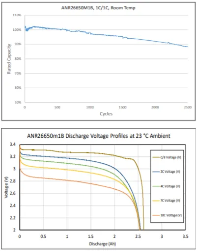
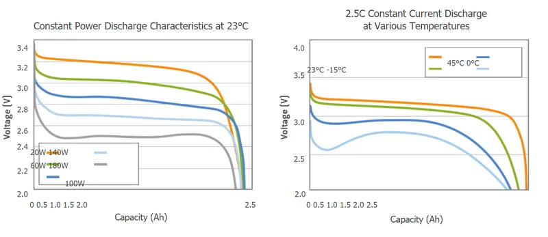
- Cycle Life at 1C/1C, 100% DOD, > 4000 cycles
- Safety: Excellent abuse tolerance and environmentally friendly
- Life: Excellent calendar life, 10X cycle life vs. conventional lithium ion
Nanophosphate Technology
ANR26650M1-B low impedance Nanophosphate electrode technology provides significant competitive advantages overalternative battery technologies, including:
• Power: ANR26650M1-B Nanophosphate products can pulse at high discharge rates to deliver unmatched power by weight or volume.
• Safety: ANR26650M1-B Nanophosphate technology is designed to be highly abuse-tolerant, while meeting the most demanding customer requirements of power, energy, operating temperature range, cycle life, and calendar life.
• Life: ANR26650M1-B Nanophosphate technology delivers exceptional calendar and cycle life. cells can deliverthousands of 100% Depth-of-Discharge (DOD) cycles, a feat unmatched by other commercial lithium ioncells
Let us assume that the voltage of the battery pack (Pack Voltage) = 400 V
We know that P = VI, hence we can calculate the Pack Capacity as follows:
Pack Capacity = Energy Capacity / Pack Voltage
Pack current Capacity = (18*103) / 400 = 45 Ah
No. of cells in series = Pack Voltage / Cell Voltage = 400 / 3.3 = 121.21 ≈ 122 cells
No. of cells in parallel = Pack Capacity / Cell Capacity = 45 / 2.5 = 18 cells
Total no. of cells in the battery pack = (No. of cells in series) * (No. of cells in parallel)
= 122 * 18 = 2196 cells
Weight of battery pack = (Total no. of cells in the battery pack) * (Cell Weight)
= (2196 * 76) / 1000 = 166.89 kg ≈ 167 kg
Length of battery pack = (No. of cells in series) * (Cell Diameter)
= 122 * 0.026 = 3.172 m
Width of battery pack = (No. of cells in parallel) * (Cell Diameter)
= 18 * 0.026 = 0.468 m
Area of battery pack = (Length of battery pack) * (Width of battery pack)
= 3.172 * 0.468 = 1.4845 m2
Volume of battery pack = (Area of battery pack) * (Cell Height)
= 1.4845 * 0.065 = 0.0965 m3 = 96.5 litres
Specific Energy Density = Pack Energy Capacity / Weight of battery pack
= (18 * 103) / 167 = 107.78 Wh/kg
Volumetric Energy Density = Pack Energy Capacity / Volume of battery pack
= (18 * 103) / 96.5 = 186.53 Wh/L
Cost of battery pack = (Total no. of cells in the battery pack) * (Cost of each cell)
= 2196 * 6.55 = $ 14,383.8 = Rs 10,45,544.76
BATTERY DESIGN
A battery pack is a system of multiple components and functions and its design involves the application ofknowledge and practice in the electrochemical, electrical, mechanical, thermodynamic, and control fields. Thefollowing sections summarize the various stages of a battery pack design, covering specific aspects of the ANR26650M1.
1.

The first step in the design of the pack is to determine the configuration of cells, i.e. how many cells overall, how many are inseries, and how many are in parallel. This is the foundation of the design process, since all other design decisions follow from the cell configuration.
No. of cells in series = Pack Voltage / Cell Voltage = 400 / 3.3 = 121.21 ≈ 122 cells
No. of cells in parallel = Pack Capacity / Cell Capacity = 45 / 2.5 = 18 cells
Total no. of cells in the battery pack = (No. of cells in series) * (No. of cells in parallel)
= 122 * 18 = 2196 cells
Configuration of Cells in a Battery Pack
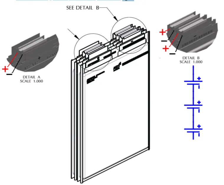
The battery pack’s terminal voltage and current ratings must match those of thedevice(s) to which it interfaces. If the pack requires the energy of just one cell, the designer’s options are limited to the ratings of that one cell. However, as moreenergy is required of the pack, requiring more cells to be interconnected, the
degrees of freedom increase, allowing the designer to choose a combination of cell-to-cell interconnections thatprovide the right voltage and currents to interface properly in the application. Once a configuration of cells ischosen, the designer must insure that the resulting ratings of the pack are compliant with the systems that willconnect to it. This section covers:
• Voltage and Capacity
• Series Strings
• Parallel Cells
Voltage and Capacity
Cells can be combined together either in series or in parallel to achieve higher operating voltages and power,respectively. This section describes the electrical aspects of interconnecting cells
Let us assume that the voltage of the battery pack (Pack Voltage) = 400 V
We know that P = VI, hence we can calculate the Pack Capacity as follows:
Pack Capacity = Energy Capacity / Pack Voltage
Pack Capacity = (18*103) / 400 = 45 Ah
Series Strings
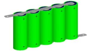
Cells combined in series strings will achieve higher operating voltages by connecting the positive terminal ofone cell to the negative terminal of the next cell. Connect strings of series AMP20 cells using their currentcollection tabs in a manner similar to that illustrated in Figure
Connect strings of series cylindrical cells using their current collection tabs in a manner similar to that illustrated in the figure.
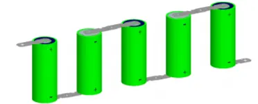
No. of cells in series = Pack Voltage / Cell Voltage = 400 / 3.3 = 121.21 ≈ 122 cells.
122 cells are comnnected in series
Parallel Cells
Cells connected in parallel can achieve higher operating power by connecting like-polarity terminals of adjacent
cells to each other. Connect groups of parallel cells using their current collection tabs in a manner similar to that
illustrated in Figure
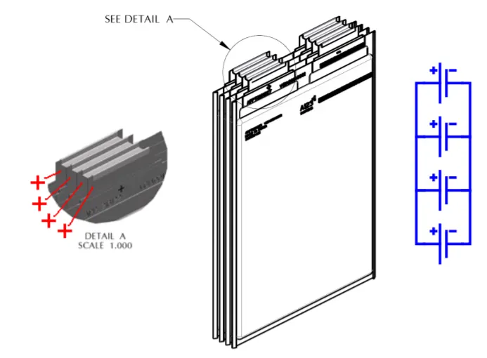
Connect groups of parallel cylindrical cells using their current collection tabs, to connect positive-to-positiveterminals of adjacent cells and negative-to-negative terminals of adjacent cells in a manner similar to thatillustrated in the figure below:
No. of cells in parallel = Pack Capacity / Cell Capacity = 45 / 2.5 = 18 cells
18 cells are connected in parallel
2.

The second step is to design a mechanical structure around the cells to support and protect them. This step requires knowledge of electrical,mechanical and thermodynamic requirements and properties of the cells, application, and the materials used in the pack.
Weight of battery pack = (Total no. of cells in the battery pack) * (Cell Weight)
= (2196 * 76) / 1000 = 166.89 kg ≈ 167 kg
Length of battery pack = (No. of cells in series) * (Cell Diameter)
= 122 * 0.026 = 3.172 m
Width of battery pack = (No. of cells in parallel) * (Cell Diameter)
= 18 * 0.026 = 0.468 m
Area of battery pack = (Length of battery pack) * (Width of battery pack)
= 3.172 * 0.468 = 1.4845 m2
Volume of battery pack = (Area of battery pack) * (Cell Height)
= 1.4845 * 0.065 = 0.0965 m3 = 96.5 litres
Battery Pack Structural Design
A well designed battery pack protects and replicates the individual cell performanceof multiple cells in the pack. It provides mechanical protection and integrity,
thermal stability, and electrical protection and performance. The electricalinterconnections, mechanical supports and thermodynamic systems are all essentialelements of the battery pack’s structural design. This section covers:
• Electrical Connection and Protection
• Mechanical Cell Support
• Thermal Management
Electrical Connection and Protection
The electrical interconnections in a battery pack must be designed to carry the expected maximum current for both the maximum time and ambienttemperature in which the pack is expected to operate. In addition, theelectrical interconnections shall be designed to prevent accidental short circuits that may result from heavyvibration (vehicle operation), or extreme shock (drop or impact), or loose hardware.
Cell Interconnections
Cell interconnections should be sized for the expected maximum current carrying capability. Improperly sized interconnections could heat up excessively, resulting in damage to themselves, nearby components, structures or even the cells. For reliable welded connections at cell terminals, recommends either copper or copper alloy straps welded to the copper tabs and aluminum straps welded to the aluminum tabs. cylindrical cells, cell interconnections (straps) should be neither soldered on the cells tabs nor attached using extreme heat. this cell recommends nickel or copper alloy straps be resistance or laser-welded to the terminals of thecells.
The outside of the prismatic cell is electrically isolated from the electrode terminals but at a high enough voltage(> 2500 Vrms Hi-Pot testing), a flashover can occur. Therefore in the battery pack design, it is important that thereis adequate and consistent insulation between the outer surfaces of the cell and any surrounding conductive surfaces, such as heat sinks, conductors, and/or the chassis.
Cylindrical Cell Insulation
The outside case of the ANR26650 is electrically connected to the positive end (cathode) of the cell.Take careto keep this surface electrically-isolated from any electrical bus bar or mechanical support that may be of differentvoltage potential. Insulation, such as tapes, shrink wraps, or sleeves, must have at least a 150 °C melting point. This helps ensure that the cells do not short circuit to each other in a high temperature fault condition, which could cause even more widespread damage.
Mechanical Cell Support
Secure the cells in place by supporting their outside cases, not their terminal ends. The vibration induced betweenthe terminal ends and the rest of the case has been shown to be detrimental to the life of the cell, causing internal and external cell damage. The inter-cell terminations must be light enough not to cause vibration-induced damage
to the cel
Thermal Management
Cells operate very well in a wide temperature range; however, they are most effective between 10 °C and50 °C. The temperature differential between the coolest cells and the hottest cells should be no more than 10 °C.Careful attention to thermal management is necessary to keep the cells operating at peak efficiency and avoiding fault conditions. In most cases, this will require a cooling system. There are certain applications - such as PHEV vehicles operating in cold climates – in which a heater is beneficial to keeping the cells operating in their optimal range.
3.
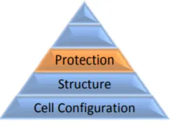
The third step is to design the protection of the cells, particularly electrical protection. The pack must be protected from in advertentshort circuits internal and external to the pack as well as excessivecharging and discharging imposed on its terminals.
Overcharge Protection
The only way to provide fool-proof protection from overcharging the cells in a pack is to interrupt the currentwhen such a condition is sensed. Electronic switches, relays or contactors can be used to interrupt the currententering the cells. Electronic circuitry monitoring each cell can be used to trigger the interrupting device when anycell voltage goes outside of its safe operating range.
Cell Environmental Protection
In addition to supporting the cells, a well-designed chassis will protect cells from exposure to corrosive substances and oxidizing catalysts, such as dust and moisture. The necessary level of protection for cells in a battery pack varies depending on the intended application. For example, a battery pack designed for use in a vehicle must have an enclosure that isolates cells from shock and vibration, protects them from dirt and debris, as well as shieldingthem from other environmental dangers, such as salt spray. Unless it is hermetically sealed, even a sealed enclosure is subject to pressure differentials between its insides and the ambient, causing minute amounts of air exchange. Therefore, over time, some moisture may accumulate and condense on inside surfaces. A battery pack designed to be sealed from the environment (from dust, moisture, and volatile chemicals) must have a way to benignly drain off whatever condensate does manage to leak into it and keep it away from circuits and conductors. In addition, enclosures protecting cells must work with the thermal management system to achieve optimum durability and safety of the battery pack. For example, a poor choice of materials for the enclosure, combined with insufficient cooling and controls, may cause the battery pack to overheat.
ANR26650 Cell Vents
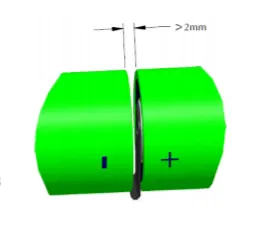
The ANR26650 cell vents, located on the end cap(s) of the cells (on the POSITIVE side of the cell), should not be blocked by any mechanical means.
Blocking the cell vent and then sufficiently abusing the cell so as to build up pressure in the cell prevents the cell from properly venting. A battery packdesigned to install cells end-to-end needs at least 2 mm of space between the cells to allow the vent to open under fault conditions.
4.
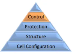
The fourth step is to design a control system that monitors and manages the cells, keeping them from being damaged and maintaining the pack at peak performance.
When joining cells together, cell recommends using a Battery Management System(BMS) to accurately monitor cell voltage, current, impedance and other conditions of the cells. The BMS may be implemented as discrete circuitry and/or through a microcontroller.
BMS
Sofware is a major component of lithium-ion battery packs, particularly for automotive applications. The software is implemented using the Battery Management System (BMS). Control systems are required to keep the cells within their specified operating range and to protect them from abuse. Fuel gauging needs complex algorithms to estimate the state of charge (SOC). Communications with other vehicle systems are needed for monitoring the battery status and controlling energy flows.
• Cell Monitoring
• Supervising Battery Pack Behavior
• Cell Balancing
• Fuel Gauging
• Integrated Circuits
5.
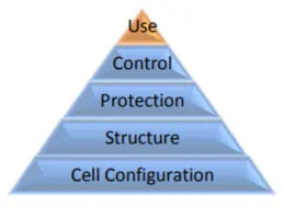
a pack performs best when it is used properly. The final section describes how to charge and discharge the battery packto make it perform its best.
When charging and discharging a battery pack, the current and voltage applied to any cell in the pack shall not be exceeded for the given conditions under which the cell are exposed. Appendix A details the limits within which the cells must be kept for a given cell’s temperature and cell’s state of charge. The points in use are
• Charger Limits
• Discharging Current Limits
• Discharging Cell Temperature Limits
APPLICATIONS
TRANSPORTATION SOLUTIONS
Hybrid, plug-in hybrid and electric vehicle battery systems for:
Commercial vehicles
Off-highway vehicles
Passenger vehicles
CONCLUSION
By the cell specifications Any type of required batteries can be made