Project 1 Mechanical design of battery pack
Mechanical design of battery pack
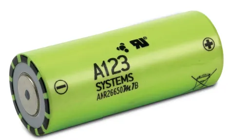
Nanophosphate® High Power Lithium Ion Cell ANR26650M1-B
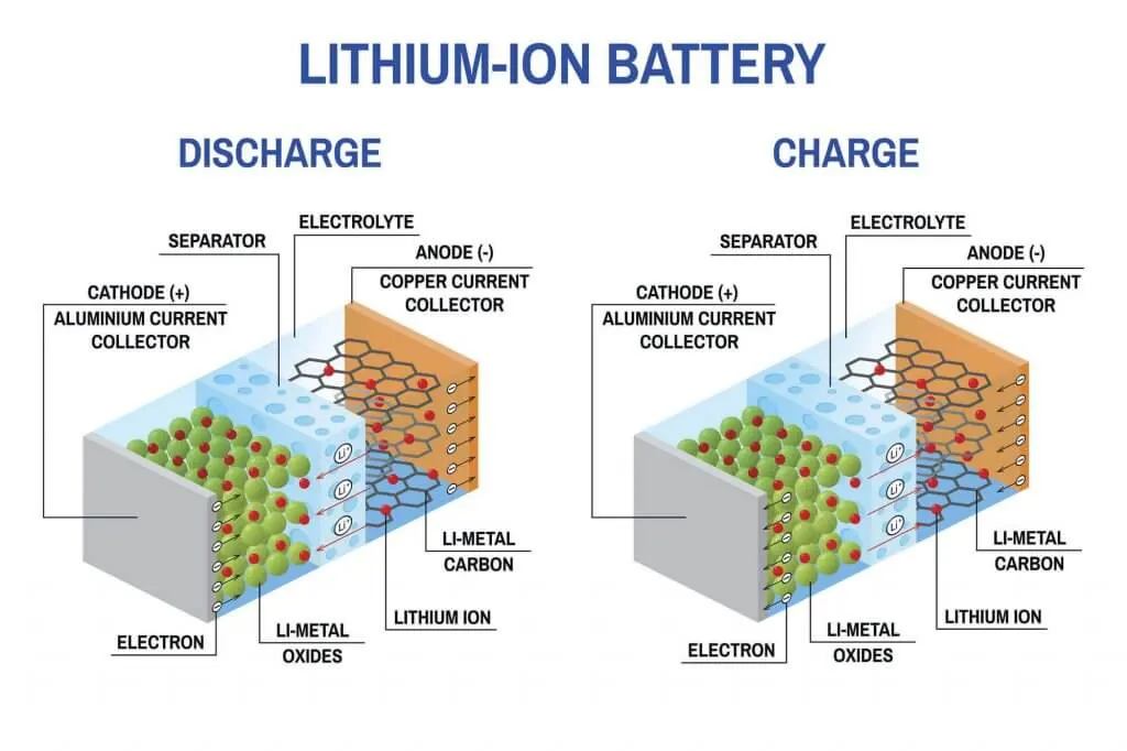
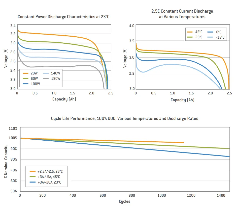
The Nanophosphate® High Power Lithium-Ion Cell ANR26650M1-B, developed by A123 Systems, is a high-performance lithium iron phosphate (LiFePO₄ or LFP) battery cell designed for applications requiring high power output, fast charging, and long cycle life. With a nominal voltage of 3.3V and a capacity of 2.5Ah, this cylindrical 26650-format cell offers exceptional power density, supporting continuous discharge rates of up to 70A (28C) and peak pulse discharges exceeding 120A. One of its standout features is Nanophosphate® technology, which enhances thermal stability, safety, and efficiency compared to conventional lithium-ion chemistries. It also provides an impressive cycle life, exceeding 2,000 charge-discharge cycles while maintaining consistent performance. The ANR26650M1-B is widely used in electric vehicles (EVs), hybrid vehicles (HEVs), power tools, aerospace, industrial applications, and renewable energy storage systems. Its robust design ensures low risk of thermal runaway, making it a safer alternative to cobalt-based lithium-ion batteries. Additionally, its ability to handle fast charging and high discharge currents makes it an ideal choice for demanding applications where reliability and efficiency are paramount.
DESIGN CALCULATION
The capacity of the battery pack is set to be 18kWh.
For making a high voltage battery pack many cells are arranged in a particular pattern and sequence to improve the voltage and the power rating. Individual battery cells may be grouped in parallel and/or series as modules. Further, battery modules can be connected in parallel and/or series to create a battery pack. Depending on the battery parameters, there may be several levels of modularity.
The total battery pack voltage is determined by the number of cells in series. For example, the total (string) voltage of 6 cells connected in series will be the sum of their individual voltage.
In order to increase the current capability of the battery capacity, more strings have to be connected in parallel. For example, 3 strings connected in parallel will triple the capacity and current capability of the battery pack. Now for calculating our required battery pack based on the cell manufacture data provided.
The calculation for the battery pack is as follows.
Battery Pack Calculation for ANR26650M1-B Cells with capacity: 18 kWh
Design a 18 kWh battery pack with a 400V nominal voltage configuration
1. Battery Pack Configuration
Step 1: Understand the Cell Specifications
- Nominal Voltage of each cell: 3.3V
- Capacity of each cell: 2.5 Ah
- Energy per cell: Energy per cell=Nominal Voltage × Capacity=3.3V×2.5Ah=8.25Wh
Step 2: Total Energy Requirement
- The desired total energy capacity for the pack is 18 kWh, or 18,000 Wh.
- To determine how many cells are needed, we divide the total energy by the energy per cell
- Number of cells (total) = Total Energy/Energy per cell = 18,000Wh/8.25Wh ≈ 2182 cells
So, we need approximately 2,182 cells in total.
2. Number of Cells in Series
Step 1: Determine the Series Configuration (Voltage)
Since we want a 400V nominal voltage pack, and each ANR26650M1-B cell has a nominal voltage of 3.3V, we need to calculate the number of cells to connect in series to achieve the desired voltage.
- Number of cells in series (S)=Desired Voltage/Voltage per Cell=400V/3.3V≈121.2
Therefore, we will round up to 122 cells in series (121 would give approximately 401.3V, which is too high).
So, we need 122 cells in series to achieve a nominal voltage close to 400V.
Step 2: Voltage per Series String
The voltage of each series string will be:
- Voltage of Series String=122×3.3V=402.6V
This will give us a nominal voltage of approximately 400V, which is suitable.
3. Number of Cells in Parallel
Now that we know the number of cells in series (122), we can calculate the number of cells in parallel needed to achieve the desired total capacity of 18 kWh.
Step 1: Energy per Series String
Each series string will have 122 cells in series, and the capacity per cell is 2.5Ah. The energy per series string is:
- Energy per Series String=Voltage of Series String × Capacity per Cell = 402.6V × 2.5Ah = 1006.5Wh
Step 2: Number of Parallel Strings (P)
We now calculate how many parallel strings of 122 cells we need to achieve a total energy of 18,000Wh:
P = Total Energy/Energy per Series String = 18,000Wh/1006.5Wh ≈ 17.9P
We will round up to 18 parallel strings to ensure the required capacity.
4. Total Number of Cells
Now that we know we need 122 cells in series and 18 parallel strings, we can calculate the total number of cells in the pack:
Total number of cells = Number of Series Cells × Number of Parallel Strings = 122×18 = 2,196 cells
5. Enclosure Size Calculation
Step 1: Cell Dimensions
The ANR26650M1-B cell has the following dimensions:
- Diameter: 26mm (2.6cm)
- Height: 65mm (6.5cm)
Step 2: Calculate the Enclosure Dimensions
For the 15S × 146P configuration, the layout is 18 parallel strings (18P) and 122 series cells (122S). So:
- Width (parallel cells in one row): Width=18×2.6cm=46.8cm
- Length (series cells in one column): Length=122×2.6cm=317.2cm
- Height: The height of the cells is 6.5cm. To account for the spacing and additional components like busbars and insulation, we add 2cm: Height=6.5cm+2cm=8.5cm
Step 3: Add Buffer for Enclosure
To account for proper insulation, busbars, wiring, and air cooling, we will add a buffer of 3cm on each side.
- Final Width=46.8cm+3cm=49.8cm
- Final Length=317.2cm+3cm=320.2cm
- Final Height=8.5cm+3cm=11.5cm
So, the final enclosure dimensions are approximately: 49.8cm×320.2cm×11.5cm
Step 4: Thermal Management and Cooling
- Airflow: Since the pack will generate heat during charge/discharge cycles, air vents and cooling fans should be integrated into the design to allow for proper airflow.
- Liquid Cooling (Optional): If higher cooling performance is needed, cooling plates with liquid channels can be added along the cells to improve thermal performance.
6. Electrical Connections
Busbars
- Series Connections: Copper or aluminum busbars should be used to connect 122 cells in series.
- Parallel Connections: Each of the 18 parallel strings should have parallel busbars connecting the positive and negative terminals.
BMS Integration
- Voltage Sensing: The BMS will monitor the voltage of each cell or group of cells in the series.
- Temperature Sensors: Temperature sensors should be placed throughout the battery pack to monitor each string's temperature.
Fuse Protection
- Fuses should be placed on both the positive and negative terminals of the battery pack to prevent overcurrent conditions.
Summary Battery Pack & Enclosure
- Series Configuration: 122 cells in series (to achieve 400V nominal voltage).
- Parallel Configuration: 18 parallel strings (to achieve 18 kWh capacity).
- Total Number of Cells: 2,196 cells.
- Enclosure Dimensions: 49.8cm × 320.2cm × 11.5cm.
- Electrical Connections: Copper busbars for series and parallel connections, and BMS integration for monitoring.
Assembly of the battery pack
Component of the battery pack:
- 300 cells
- Nickel strip
- PVC heat sink film
- spot welder
- Connected
- Cell holder
- Solder
Step 1 -
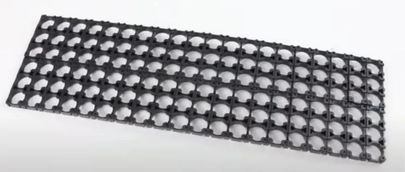
The first step is to start snapping the square cell holder together. One can use the cell terminal block but they will take more space than a hexagonal block.


Step 2 -
Placing the cells in the holder matrix. Place all the cells in the holder and put the second holder in the place.
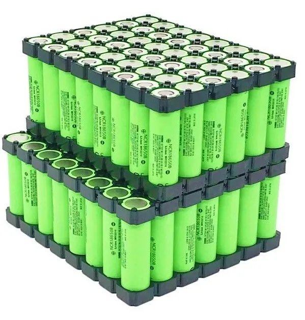
Step 3 -
Now we will be connecting the cells with nickel strips using the spot welding process. The series connection will be made by connecting the positive terminal of the cells to the negative terminal. The parallel connection will be made by connecting the same terminal. Connecting the complete matrix of the cell together.
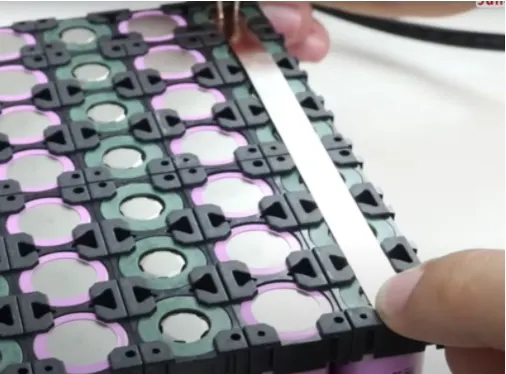
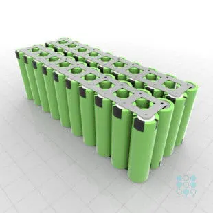
Step 4 - Connecting the heat sink to the battery pack and soldering the battery wire. The internal structure of the battery pack is assembled and all the terminals are connected as per the connections.
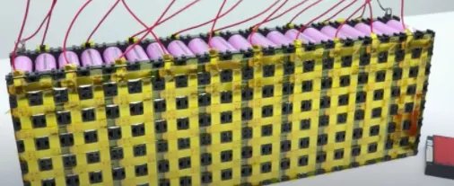

Step 5 -
Connect the balancing wire pin to the battery management system.

Step 6
After the battery management system, the next and final step is to place the enclosure for the battery pack.
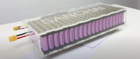
Conclusion:
The design of the 18 kWh battery pack with a 400V nominal voltage configuration using ANR26650M1-B cells involves a series connection of 122 cells in series and 18 parallel strings, resulting in a total of 2,196 cells. The pack’s energy capacity meets the desired 18 kWh, with the overall dimensions of the enclosure being approximately 49.8 cm × 320.2 cm × 11.5 cm to accommodate all cells, wiring, and necessary cooling components. Proper thermal management, busbars, BMS integration, and fuse protection are critical for ensuring safe operation and longevity. This configuration provides a robust foundation for high-performance applications in electric vehicles or energy storage systems, with scalability and efficiency in mind.