Project 1 Mechanical design of battery pack
A 123's high-performance Nanophosphate lithium iron phosphate (LiFePO4) battery technology delivers high power and energy density, excellent safety performance, and extensive life cycling in a lighter-weight, more compact package. Our cells have low capacity loss and impedance growth over time and high usable energy over a comprehensive state of charge (SOC) range, allowing our systems to meet end-of-life power and energy requirements with minimal pack oversizing.
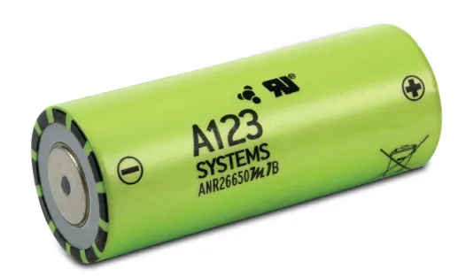
Nanophosphosate battery technology offers thermal-stable chemistry, faster charging, consistent output, low capacity loss over time, and superior total cost of ownership (TCO). It provides the foundation for safe systems while meeting customer requirements. Multiple layers of protection are employed at the chemistry, cell and system level to achieve an energy storage solution with superior safety and abuse tolerance compared to metal oxide lithium-ion chemistries.
Applications
- Energy storage
- Frequency regulation
- Uninterruptible Power Supplies
- Communication Technologies
- Aviation/Aerospace
- Electrified Mobility Devices
- Industrial Equipment
- Medical Devices
- Consumer Products
Specs for ANR26650M1B
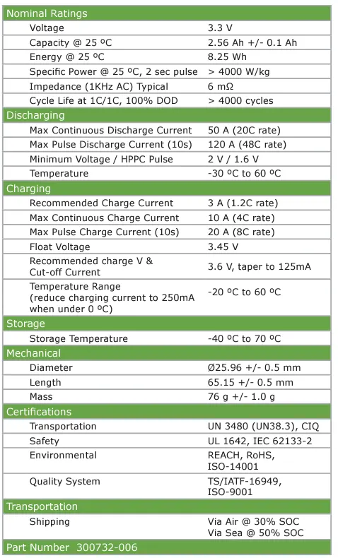
Cell Data
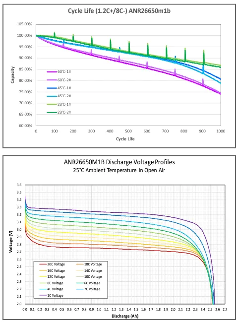
Battery Pack Use
When charging and discharging a battery pack, the current and voltage applied to any cell in the pack shall not be exceeded for the given conditions under which the cells are exposed.
Charger Limits
When charging or recharging lithium cells in a battery pack, the charger should limit its output current and voltage to match that of the battery pack configuration. During recharge, the charger shall apply a constant current (CC) charge followed by a constant charge. In addition, the charger shall cease charging when either:
- Any one cell in the series string has exceeded its maximum recommended charge voltage or
- The pack's temperature has exceeded the recommended range for charging.
To achieve maximum life, reliability, and safety, lithium cells are recommended using cell balancing circuitry to prevent an increasing spread between the highest and lowest battery states of charge.
To determine the charge current for a parallel string of cells, multiply the number of parallel cells in the string by the recommended charge current for a single cell.
Number of cells in parallel x Recommended Charge Current per cell = Charge current per string
To determine the end-of-charge voltage for a series string of cells, multiply the number of series elements in the string by the recommended charge voltage of a single cell.
Number of cells in series x Recommended Charge Voltage per cell = Charge Voltage per string
Example 1:
If a cell group has 3 cells in parallel (3P), and the recommended charge current per cell is 20 A, then the charge current for this group is 60 A.
Example 2:
If a cell string has 10 cells in series (10S), and the recommended charge voltage per cell is 3.6 V, then the end-of-charge voltage for the string is 36 V.
Once the end-of-charge voltage has been reached, apply a constant voltage hold at this voltage until the current decays to near zero. This process charges the cells to a 100% State of Charge (SOC).
Assumptions:
We are assuming the overall voltage required to operate the motor and other accessories of the electric vehicle is 600 V. So now we have to construct a battery pack of 18 kWh for a 600 V input voltage motor.
Design of Battery Pack:
- Initially, we have to estimate the voltage requirement of the vehicle's overall load to design a battery pack. We had assumed 600 V, as mentioned above.
- Then, the battery modules should be created to match the overall voltage with the load requirement voltage.
- The modules can be created in series/parallel connections of individual cells. Then, every module should be connected in series/parallel to construct the final battery pack.
- In our case, the single-cell voltage is 3.3 V and has a capacity of 2.56 Ah. The energy provided by a single cell is given 8.448 Wh. So, we need approximately an 18 kWh battery pack of (18000/8.448 =) 2130 cells.
- We must create a single module to produce 600 V for our load requirement. So to obtain 600 V output, cells are connected in series where voltage becomes added and current remains the same. To get 600 V, the number of cells required is approximately (600/3.3 =) 182 cells.
- Thus, a single module gives 600 V from 182 cells, but the energy of one module is not enough to run the vehicle as the motor power rating is higher. The energy generated from the single module is (182 x 8.448 =) 1538 Wh.
- So, to construct a battery pack with 18 kWh with not exceeding 600 V, the modules are connected in parallel. In this parallel connection, the currents are added, and the voltage remains at 600 V. As the current increases, the battery pack's power increases to run the high-power rating motor load.
- This can be calculated as 18 kWh/1538 Wh = 11.7, which gives nearly 12 similar modules that should be connected in parallel to achieve an 18 kWh battery pack.
- Thus, the battery model is said to be 182S12P configuration (182 series and 12 parallel connections), which gives us (182 x 12 =) 2184 cells. From this, we have created the overall capacity of the battery pack as (2184 x 8.448 Wh =) 18.45 kWh, which is slightly higher than 18 kWh.
- The battery pack's overall capacity (Ah) is (2.56 x 18 =) 46.08 Ah. It continuously provided 46.08 A of current for 1 hour to full discharge.
Thus, 12 modules should be arranged so the battery pack fits in an EV chassis.
Enclosure Construction:
- To find the overall enclosure volume, we have to find the single module volume consisting of 182 cells in series connection and multiplied with 12 parallel connected module volume.
- Let us assume 182 cells (single module) are divided into two modules of 91+91 cells.
- The length of the module = No. of cells in a row x (Cell diameter + Margin at both side of cells) + clearance at side [2 x (cell diameter + margin)] = 91 x (26+4) + 60 = 2790 mm = 2.79 m ≈ 2.8 m
- The breadth of the module = Cell diameter + Margin of both side of cells + Clearance = 26 + 4 +60 = 90 mm = 0.09 m
- Height of the module = Height of the cell + Connecting strip thickness, wires say 35 mm = 65 + 35 = 100 mm = 0.1 m
- Thus, the volume required for the single module is (2.8 x 0.09 x 0.1 =) 0.0252 m3.
- The total number of modules assumed is 12 x 2 = 24 since a single module is divided into two modules.
- Therefore, the total volume required for the battery pack of 182S12P configuration construction is (0.0252 x 24 =) 0.6048 m3.
- Thus, from the above results, it is assumed that approximately one m⊃3; of volume should be used for the EV battery pack with additional ventilation spaces.
We can assume that two modules are combined into one cabinet. So, 18 cabinets should be connected to form the final battery pack.
Battery Cell Manufacturing Process
1. Electrode Manufacturing
Step 1 - Mixing
- The anode and cathode materials are mixed before being delivered to the coating machine. This mixing process takes time to ensure the homogeneity of the slurry.
- Cathode: Active material (e.g. NMC622), polymer binder (e.g. PVdF), solvent (e.g. NMP), and conductive additives (e.g. carbon) are batch mixed.
- Anode: Active material (e.g. graphite or graphite + silicon), conductive material (e.g. carbon black), and polymer binder (e.g. carboxymethyl cellulose, CMC)
- N-Methyl-2-Pyrrolidone (NMP): This is a toxic substance widely used in the plastics industry as it is non-volatile and can dissolve many materials. NMP residual will be a Quality Control test downstream as that will affect cell performance reactively.
Challenges:
- Homogeneity of the mix.
- Ensuring low ppm H2O - Suppliers will be asked to guarantee a low ppm.
- No breakup of the particles.
- Particle and pore size distribution will be targeted with suppliers or via in-process Milling. Some developments concentrate on producing dual layers (to form a quasi-heterogeneous bi-layer).
Step 2 - Coating
The anodes and cathode are coated separately in a continuous coating process. The cathode (metal oxide for a lithium-ion cell) is coated onto an aluminium electrode. The polymer binder adheres to anode and cathode coatings to the copper and aluminium electrodes.
Challenges
- Controlling thickness and thickness over time: Control across the width of the web can be more challenging than control along the length.
- One of the biggest challenges is getting the edges right:
1. Getting the width exactly right down to 0.1 mm → Shim adjustments can solve this.
2. Avoiding/Controlling any "Fat Edges", i.e. thickness build-ups at the edges → Also Shim adjustments.
3. Make sure the edges are always straight and do not show waviness → Slot die distance to the substrate and slot die angle need to be controlled and adjusted correctly. - Foil surface oxidation homogeneity can add variance to the challenge.
- Controlling foil moisture levels.
- Besides thickness, tensiometer peel tests and even indentation resistance (hardness test) might be used to qualify the coating integrity further.
Step 3 - Drying
Immediately after coating, the electrodes are dried. This is done with convective air dryers in a continuous process. The solvents are recovered from this process.
Infrared technology is used as a booster on anode lines.
Challenges
- Centre to edge homogeneity of the drying process.
- Recovering solvent
- Avoiding cracking
Step 4 - Calendering
This is a rolling of the electrodes to a controlled thickness and porosity.
Challenges
- Controlling uniform thickness.
- Avoiding cracking
2. Cell Assembly
Step 5 - Slitting
The electrodes up to this point will be in standard widths up to 1.5 m. This stage runs along the length of the electrodes and cuts them down in width to match one of the final dimensions required for the cell.
No burrs must be created on the edges of the electrodes during this process, as they can cause damage to the separator and a possible short-circuit later.
- Avoiding burrs on edges
→ Insulation tape may be applied here to mitigate foil-to-foil shorts from burrs. - Ensuring no loose metallic particles contaminate coatings.
Step 6 - Final Drying
The electrodes are dried again to remove all solvent content and to reduce free water ppm prior to the final processes before assembling the cell.
Step 7 - Cutting
The final shape of the electrode, including tabs for the electrodes, is cut. At this point, you will have electrodes that are precisely the correct shape for the final cell assembly.
Challenges
- Avoiding burrs on edges
- Ensuring no loose metallic particles contaminate coatings
Step 8 - Winding or Stacking
In a cylindrical cell, the anode, the cathode, and the separator are wound into a spiral. For pouch cells, the electrodes are stacked: anode, separator, cathode, separator, anode, separator, etc.
Some prismatic cells have stacked electrodes, and some have a flat wound jelly roll.
Challenges
- Alignment of layers
- Avoid punctures of the separator
- Separator folding
→ Lots of countermeasures applied over time, like separator envelope welding; not all manufacturers countermeasures in this way. - Check humidity
→ An important test that should be done before assembly and the filling stage is checking the humidity of the separator.
Step 9 - Terminal Welding
The anodes are connected to the negative terminal, and the cathodes to the positive terminal. The process and robustness of this joint are important to understand, as welding the cell to busbars can damage the internal welds.
Challenges
- Trimming of tabs and avoiding any burrs or particles being left behind.
- Gathering all of the foils and presenting them to the welder.
- Aligning gathering electrode foils with tab.
- Weld position alignment, whether Laser Alignment, spot weld or ultrasonic horn and anvil alignment.
→ Wear of electrodes/horn/anvil.
→ Consistent energy burst, energy oscillation, changes in materials or surfaces. - Ensuring no sputter contaminates the cell.
- Ensuring good, consistent electrical connections.
Step 10 - Canning or Enclosing
The electrodes, either as a roll or pack of stacked layers, are loaded into the can or pouch. Depending on the cell format will change how this canning or enclosing process is completed.
Challenges
- Ensuring no debris in the can.
- Ensuring no damage to jelly roll or stack.
- Pouch
→ Pouch cup formation - avoid die inclusions
→ Stack placement in pouch - alignment
→ 2nd Pouch (over) cup - avoid die inclusions
→ Heat sealing integrity time, applied energy - avoid heater bar contamination affecting seal integrity.
→ Open cell seal handling prior to injection
→ Pouch Taping - A tape line is applied on the cup's inner side corresponding to the stack's placement. - Isolation Testing
→ HiPot testing or Capacitance tests are done at this stage to establish the integrity of the cell. This should find:
→ Debris/metallic foreign particles
→ Folds in the separator
→ Holes in the separator
→ Burrs on current collectors
3. Cell Finishing
Step 11 - Filling
Up until now, dry cells are filled with electrolytes. A partial vacuum is created in the cell, and a pre-determined quantity of electrolyte is delivered to the cell. The partial vacuum helps the distribution and wetting of all cell layers.
The electrolyte is dispensed based on a defined volume of liquid. A second quality check is the cell weight before and immediately after filling.
Challenges
- Environment ppm control
- "Vacuum" injection pressure integrity
- The electrolyte must be in the very low ppb range for H2O.
→ Higher levels of H2O create HF not only a safety hazard but also eats the battery from the inside out. - Mass flow injection (as opposed to volume flow injection).
- Traceability finesse of the injection tanks, purge control, downtime in pipework, etc.
- Injection and feeder tank residues (preventative maintenance control and frequency) build-up.
- Temporary seal integrity checks
- Wetting of all layers within the jelly roll or stack with electrolyte
→ May require rolling/rotation protocol to enhance wetting
Step 12 - Formation & Sealing
The cell is charged, and gases form in the cell at this point. The gases are released before the cell is finally sealed. The formation process, along with the ageing process, can take up to 3 weeks to complete.
During the formation process, a solid-electrolyte interface (SEI) develops. The SEI can prevent the irreversible consumption of electrolytes and protect the anode from overpotential during fast charging.
Challenges:
- Environmental control in charging bays during formation
- Timestamp control of the applied protocol
- Degas evacuation pressure level. e.g. electrolyte boil-off control before the permanent seal.
- Checking cell is sealed permanently
→ Mass check is often used. - Running the formation cycle without damaging the cell
Step 13 - Ageing
The cells are stored at a controlled temperature for a period of time. This allows the SEI to stabilize.
This step in the process ties up the cells for a length of time; this inventory of cells has a considerable value and hence ties up funds.
Challenges
- Forming and ageing the cell fast and delivering quality working cells.
- Fire detection in the ageing storage system.
- Reducing time for ageing and so reducing the inventory of cells.
- Multi-barrier safety environment
→ De-oxygenated environment
→ Nitrogen Dowse
→ IR Thermography
→ Fibre optic loop sensing
Step 14 - Final Control Checks
Alongside the charge/discharge cycle data, a number of further finishing steps and checks will be done before shipment:
- Delta OCV rate
- Cell Trimming
- Mass Check
- Dimension Check
- Pouch Cells
→ Leak Check
→ Thickness Check - Visual Check for Surface, TAB and SEAL anomalies.
All data is recorded against the cells' unique identification.
Enclosures
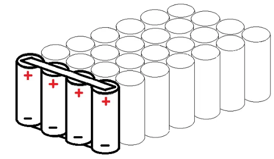
1. Cells in series connection
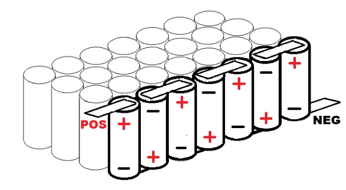
When you connect the cells together in series, it doesn't change the amps or the capacity. It only raises the voltage of the pack. Hooking them up in series means connecting the positive end of one cell to the negative end of the other, as shown below.
2. Cells in parallel connection:
If we take several cells and connect their same-type electrodes in parallel, they all act like one large cell. Also, when we first connect them to each other, they must be at the same level of charge.
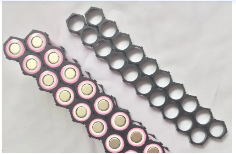
3. Cell Holders:
These holders hold the individual cell in a better posture without mis-assembling. The connections can be made accordingly to make series connections and parallel connections to form the required module dimension.
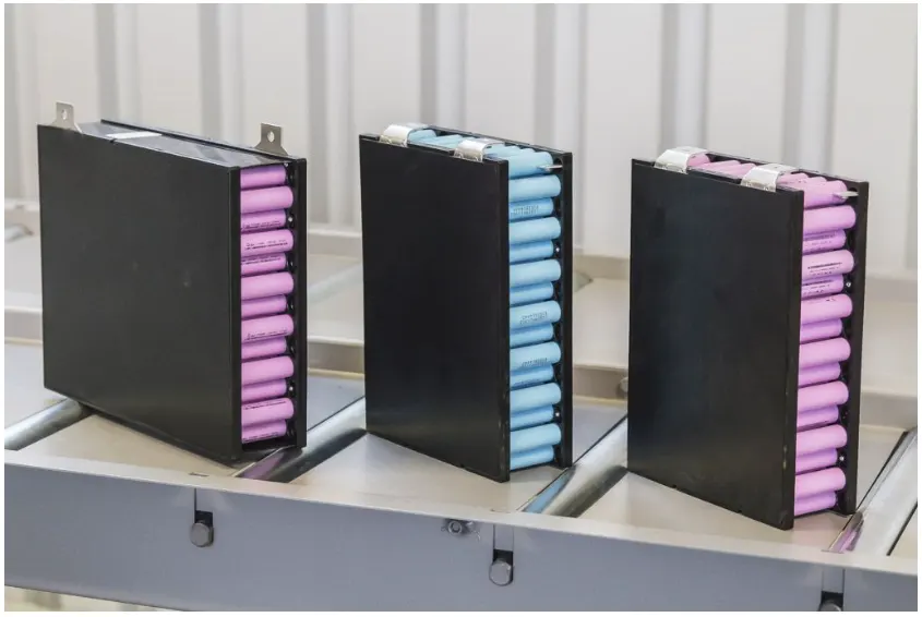
After installing the cells in an individual module, the maximum positive and negative terminals are made under a single pair of terminals, as shown below.
The cells can also be arranged and welded without using cell holders.
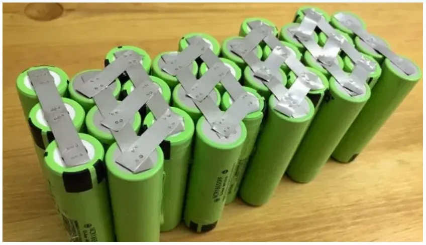
They are just covered by a polymer sheet after the interconnections are made. Mostly connections with cell holders should be recommended for better safety concerns.
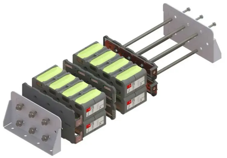
4. Battery Cabinet Arrangements
Each module is interconnected in series or parallel according to the requirement and packed as a single large cabinet pack, as shown below.
5. Battery Pack Arrangement
Finally, after arranging all cabinet connections with enclosure, the overall battery pack looks like shown below.
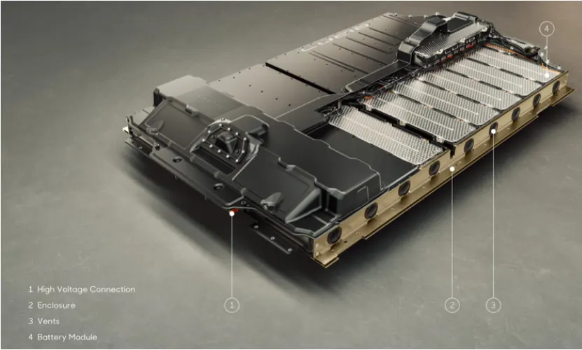
Vent holes are present with an enclosure for cooling/heating the battery pack temperature according to environmental conditions.
Conclusion:
Hence, a detailed battery pack drawing is prepared along with its enclosure, and my assumptions are stated.