Project 1 Mechanical design of battery pack
The ANR26650M1-B is a high Power Lithium Ion Cell.
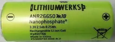
The description of the cell is as shown in the table-below.
| Part | ANR26650M1-B |
|---|---|
| Description | High Power LithiumIon Cell |
| Feature | Nanophosphate® High Power Lithium Ion C ell ANR26650M1-B A123’s high-performa nce Nanophosphate® lithium iron phosphate (LiFePO4) battery technology delivers high power and energy density combined with excellent safety performance and extensive life cycling in a lighter weight, more compact package. Our cells have a low capacity loss and impedance growth over time as well as high usable energy over a wide state of charge (SOC) range, allowing our systems to meet end-of-life power and energy requirements with minimal pack oversizing. Applications COMMERCIAL SOLUTIONS Advanced lead acid. |
| Manufacture | A123 Systems |
As per the given data, we need to design the battery pack for 18 Kwh. = P
The Total voltage of Battery pack is taken asapproximatelyy 72 V.= V
So the total number of series cells is given by :
Ns = Total Voltage of the battery pack/ Nominal Cell Voltage.
When referring to data-sheet, we get the nominal cell voltage as: 3.3 V
Ns = 72 / 3.3
Ns = 21.81 =~ 21
The number of cells in parallel connection is given by :
Np = Total current value/ Single cell capacity
Power = voltage * Current
Current = Power / Voltage
Current = 18000/72
Current = 250 A
From the datasheet, we get the value for the current as: 2.5mA @ 0.5 C. Hence at 1 C, it will be 2*0.5 C = 5Ah.
Hence the number of parallel cells in the battery pack is
Np = 250 / 5
Np= 50
Now to find the total number of cells , use the formula
Total number of cells = Number of cells in series(Ns) * Number of cells in parallel (Np)
Total number of cells = 21 * 50
Total number of cells = 1050
Now the total voltage of the battery pack is needed to be calculated.
Total Voltage inside Battery pack = Number of cells in series * Nominal voltage
Ns= 21; Nominal voltage (V nomial = 3.3 V) ;
Total Voltage inside battery pack = 21 * 3.3
Total Voltage inside battery pack = 69.3 V
Now the current is needed to be found which is given by
Total current = Np * Nominal capacity
Total current = 50 * 5
Total current = 250 A
Dimensions of the cell:
As per the datasheet the dimensions are as follows:
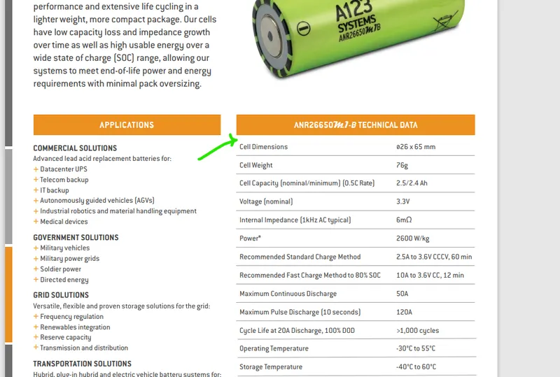
The dimensions given here are 26 mm in diameter and 65 mm is the height of the cylindrical cell.
The manufacturing process of Li-ion cells:
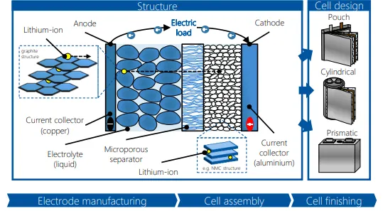
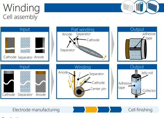
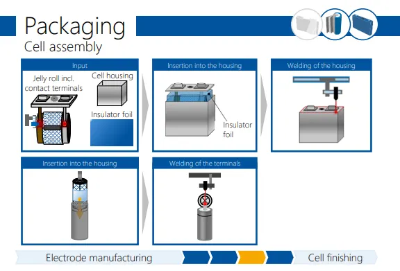
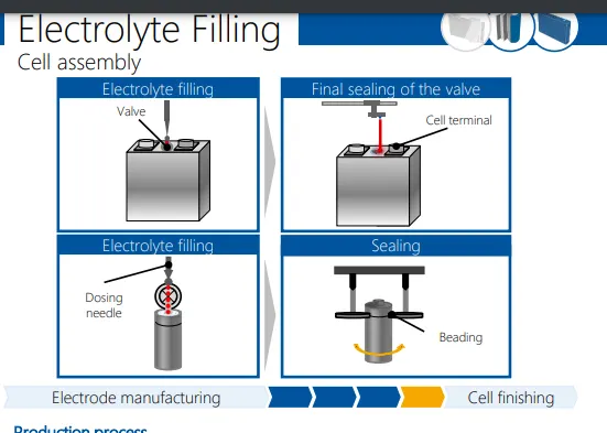
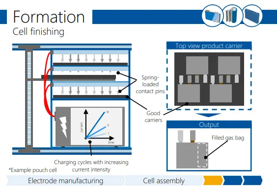
The production of the lithium-ion battery cell consists of three main process
steps: electrode manufacturing, cell assembly, and cell finishing.
● Electrode production and cell finishing are largely independent of the cell
type, while within cell assembly a distinction must be made between pouch
cells, cylindrical cells, and prismatic cells.
● Regardless of the cell type, the smallest unit of any lithium-ion cell consists
of two electrodes and a separator, which separates the electrodes from
each other. The ion-conductive electrolyte fills the pores of the electrodes
and the remaining space inside the cell.
Production process
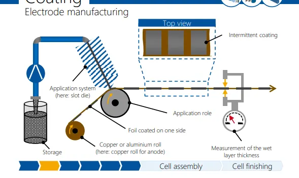
● With the help of a rotating tool at least two separated raw materials are combined to form a so-called slurry.
● The production of slurry requires not only active materials but also conductive additives, solvents, and binders.
● A distinction is made between mixing (dry mixing) and dispersing (wet mixing). In addition, the
process can be performed under a vacuum to avoid gas inclusions.
● The choice of the mixing and dispersing sequence must be adapted to the electrode design to be
produced.
Additional information
● The onward transport to the process step "coating" takes place through pipework or in sealed
storage tanks.
● Active materials, conductive additives, solvents, and binders are purchased components for many
cell manufacturers.
Production process
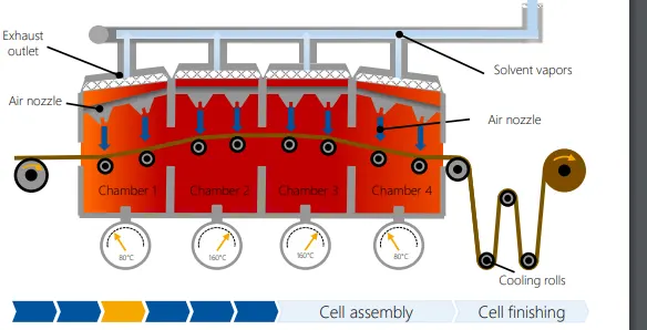
● After coating, the applied active material is dried in a continuous process.
● The solvent is removed from the material by heat supply.
● The highly flammable solvent contained in the cathode coating is recovered or used for thermal
recycling.
● The transport of the foil is realized either by roller systems or by floatation air streams. For a
simultaneous, double-sided coating, a floatation dryer must be used.
● The dryer is divided into different temperature zones to realize an individual temperature profile.
This is normally realized by a chamber system.
● After passing through the dryer, the foil is cooled down to room temperature and, depending on
the type of system, rewound (conventional) or directly coated on the second side (tandem
coating
Production process
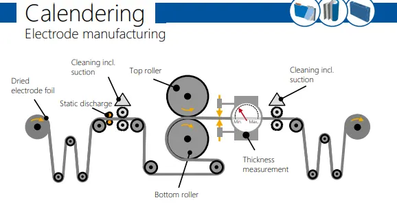
● During calendering, the copper or aluminium foil coated on both sides is compressed by a rotating
pair of rollers.
● The electrode foil is first statically discharged and cleaned by brushes or air flow.
● The material is compacted by the top and bottom rollers.
● The pair of rollers generates a precisely defined line pressure.
● After calendering, the electrode foil is cleaned and rolled up again (roll-to-roll process).
Additional information
● Line pressure defines the porosity of the coated material which influences the subsequent wetting
properties of the electrodes and the energy density of the cell.
● If the line pressure is set too high, a squeezing process occurs and leads to stress cracks.
● The cleanliness of the rollers is crucial for preventing foreign particles from penetrating the
substrate material.
Production process
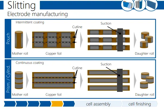
● The calendered mother rolls are usually fed to the slitting station by a manual transport process.
● Slitting is a separation process in which a wide electrode coil (mother roll) is divided into several
smaller electrode coils (daughter rolls).
● Generally, rolling knives are used for this purpose.
● The individual daughter rolls are cleaned and rewound after the cutting process (roll-to-roll
process).
Additional information
● The electrode coils are cleaned by suction and/or brushes.
● The cut quality of the electrode edges and the cleanliness of the coils are considered as the main
quality criteria.
● The cutting width of the daughter rolls can vary depending on the cell design and lies between
60 mm and 300 mm in many applications.
Production process
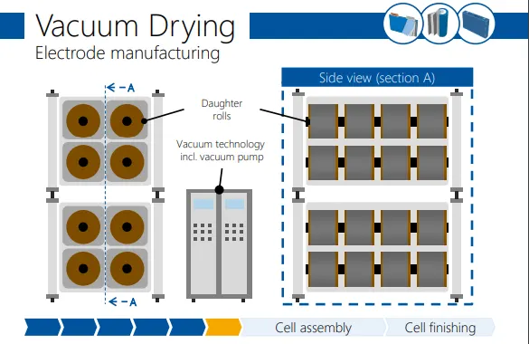
● The coated daughter rolls are pushed onto a special goods carrier.
● The coils are then stored in a vacuum oven.
● The drying time is approx. 12 h to 30 h. During the drying process, residual moisture and solvents
are removed from the coils.
● The reduction of residual moisture is achieved by evaporation at low temperatures as a result of a
low total pressure.
● After vacuum drying has been completed, the coils are transferred directly to the dry room or dry
packed under vacuum.
Additional information
● The vacuum ovens are often used as air locks into the dry room (for daughter rolls).
● In addition, it is possible to operate the vacuum ovens with inert gas in order to prevent corrosion
Production process
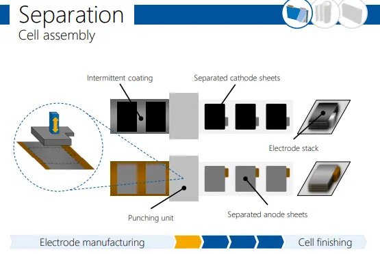
● Separation is necessary for the production of the pouch cell and describes the separation of
anode, cathode and separator sheets from the roll material (daughter rolls).
● The dried daughter rolls are unwound and fed to the separation tool.
● The cutting process is usually carried out with a shear cut (punching tool) in a continuous process.
● Depending on the system concept, the individual sheets (coated on both sides) are stored in a
magazine or transferred directly to the next process step.
Additional information
● The blank edge of the sheets are later used as the welding area for the cell tabs.
● The waste as well as the cutting dusts are extracted and transported away in the process.
Production process
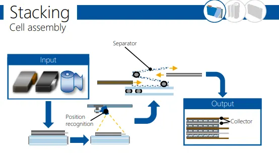
● During the stacking process the separated electrode sheets are stacked in a repeating cycle of
anode, separator, cathode, separator, etc.
● A wide variety of stacking technologies exist, which are usually patented by specific manufacturers.
● A classic variant of stacking is the so-called Z-folding.
● The anode and cathode sheets are inserted alternately from the left and right into the z-shaped
folded separator. The separator is used in the form of an endless tape and is cut off after the
stacking process.
● The cell stack is finally fixed with adhesive tape.
Additional information
● The exact positioning of the individual sheets is considered as the central quality criterion.
● The sheets are usually transported and positioned by vacuum grippers.
● Depending on the cell specification, a cell stack can consist of up to 120 individual layers

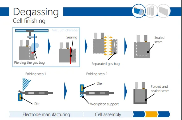
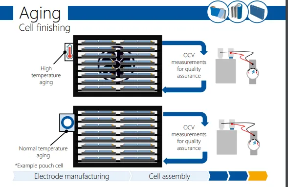
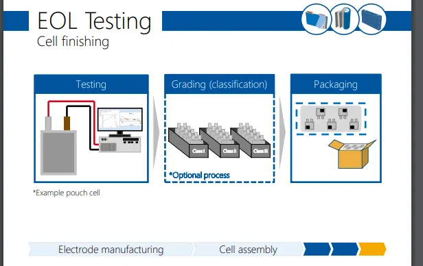
After this long process individual cells are ready to be sent to the OEMs of battery manufacturing domain. Where they can be accordingly assembled to form battery modules and battery packs which may vary as per the power rating of the vehicle.
Source : https://www.pem.rwth-aachen.de/global/show_document.asp?id=aaaaaaaaabdqbtk