Project 1 Mechanical design of battery pack
ANSWER:
What is a Battery Pack?
A battery pack is a device that stores electrical energy to provide power to an electrical system, such as an electric vehicle (EV) or an energy storage system (ESS). The energy is stored in cells that are all connected in the battery pack.
To provide sufficient power, battery packs require a minimum voltage level which a single cell cannot achieve. Multiple cells are therefore connected in series to boost voltage. Some designs use small-capacity cells. To achieve the desired battery energy, cells are connected in parallel to boost capacity. Cells connected in parallel provide power as if they were a single, larger cell.
Battery packs are made of multiple, smaller sections called battery modules (or sub-packs). These modules include a smaller number of cells connected in series and parallel. They are usually at a lower voltage, which is safe for handling. Modules facilitate servicing when only a few cells are defective and if they can be replaced without replacing the entire battery. EV batteries are typically made of 4 to 40 modules connected in series to one another.
The Components of a Battery Pack
A battery pack is the most expensive part of an electric vehicle. It is a complex system made of a wide range of components. Here are some of the important components.
- Cells are the most important components of a battery pack. The mixture of materials comprising the cell is known as its chemistry. Different battery chemistries can achieve different performances and specifications. There are two common types of cells: energy cells and power cells. There are also many variants to provide the perfect trade-off depending on the application. The lithium-ion cell (li-ion cell) is the most common chemistry in the EV industry. Alternative chemistries are sometimes used, such as Nickel-Metal Hydride (NiMH), which offers a slightly better lifecycle.
- Electrical connectors such as busbars, wires, or other distribution conductors are used to make series or parallel connections between cells and groups of cells. These connections are typically done using ultrasonic bonding or laser welding. Busbar connections between modules can also be done mechanically using fasteners.
- Thermal interface materials (TIMs) such as pastes, adhesives, and gap fillers are inserted between battery components to join them mechanically while improving thermal properties between surfaces. With the rise of the structural battery pack, TIMs are becoming essential components.
- The Battery Management System (BMS) protects cells by monitoring key parameters such as voltages, currents, and temperatures. It is responsible for cell balancing (to maintain the optimal performance of the cells at the right voltage) and communicates with several systems such as engine management and temperature control. It also includes protection devices that can shut down the battery if needed.
- The Battery Thermal Management System (BTMS) controls the thermal energy in the electric vehicle’s powertrain and cabin, providing cooling or heating as needed to meet the battery's thermal needs, and protect the cells. The BTMS includes several components such as a heat exchanger, tubes, hoses, cold plates, pumps, valves, and temperature sensors.
- The Contactor System is a switch controlled by the battery management system. It can cut off the electrical connection between the main battery and the high-voltage bus, which delivers current to the traction motor and other high-voltage components.
- The Housing is a rigid enclosure that protects the battery from environmental factors such as water, dust, and salt. It helps maintain a precise temperature and electrical insulation in the battery and prevents damage like rust and slow shorts.
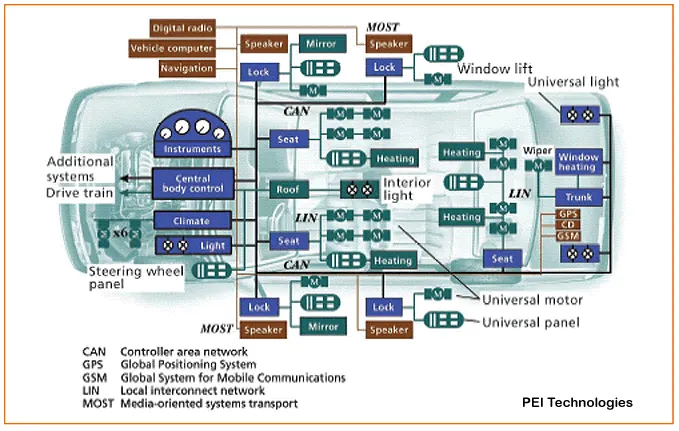
- The Communications System ensures communication with other components in the electric vehicle. The most used protocol is the CAN bus.
1. BATTERY DESIGN PACK CALCULATION:
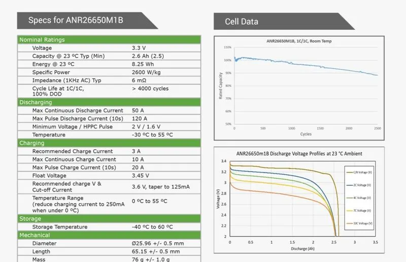
To make the battery pack, we have to finalize the pack's nominal voltage and capacity. Either it will be in terms of Volt, mAh/ Ah, or Wh.
The total required Battery pack capacity is 18000 Wh.
The individual Cell: ANR26650M1-B has
Nominal voltage = 3.3 V
Current Capacity = 2.5 Ah
1. The volume of each cell is calculated as:
- cylindrical cells, Vcc [m3]
where:
Dbc [m] – battery cell diameter=0.026m
Lbc [m] – battery cell length=0.065m
Vcc=((3.142*0.026*0.026)/4)*0.065
Vcc=0.000035
2. The battery cell energy Ebc [Wh] is calculated as:
where:
Cbc [Ah] – battery cell capacity=2.5Ah
Ubc [V] – battery cell voltage=3.3v
Ebc=2.5*3.3=8.25Wh
3. The battery cell energy density is calculated as:
- volumetric energy density, uV [Wh/m3]
- gravimetric energy density, uG [Wh/kg]
where:
mbc [kg] – battery cell mass
uG=8.25/0.076=108.55 Wh/kg
4. Total number of the battery pack
The total energy of the battery pack which is required is given as 18 kWh
Ebp=18000Wh">Ebp=18000Wh
5. The number of battery cells connected in series Ncs [-]: i n a string is calculated by dividing the nominal battery pack voltage Ubp [V] by the voltage of each battery cell Ubc [V]. The number of strings must be an integer. Therefore, the result of the calculation is rounded to the higher integer.
Let us assume that the battery pack voltage is required to be 330V and the nominal voltage of the battery as per the datasheet is given as 3.3V.
The total number of cells in the series is 100
6. The energy content of a string Ebs [Wh]: is equal to the product between the number of battery cells connected in series Ncs [-] and the energy of a battery cell Ebc [Wh].
7. The total number of strings of the battery pack Nsb :[-] is calculated by dividing the battery pack's total energy Ebp [Wh] by the energy content of a string Ebs [Wh]. The number of strings must be an integer. Therefore, the result of the calculation is rounded to the higher integer.
All 22 strings will be connected in parallel
8. We can now recalculate the battery pack's total energy Ebp [Wh] as the product between the number of strings Nsb [-] and the energy content of each string Ebs [Wh].
9. The battery pack capacity Cbp [Ah] is calculated as the product between the number of strings Nsb [-] and the capacity of the battery cell Cbc [Ah].
10. The total number of cells of the battery pack Ncb [-] is calculated as the product between the number of strings Nsb [-] and the number of cells in a string Ncs [-].
The size and mass of the high-voltage battery are verparametersnt parameters to consider when designing a battery electric vehicle (BEV). In, this example we are going to calculate the volume of the battery pack considering only the battery cells, In reality, there are other factors to consider, like electronic circuits, cooling circuits, battery casing, wiring, etc.
11. The battery pack mass (cells only) mbp [kg] is the product between the total number of cells Ncb [-] and the mass of each battery cell mbc [kg].
12. The volume of the battery pack (cells only) Vbp [m3] is the product between the total number of cells Ncb [-] and the mass of each battery cell Vcc(pc) [m3]. This volume is only used to estimate the final volume of the battery pack since it does not take into account the auxiliary components/systems of the battery.
The volume can be also calculated function of the number of strings the and number of cells in a string. This calculation method is more appropriate for cylindrical cells since the volume occupied by a cylindrical cell must take into account the air gap between cells.
13. The string peak current Ispc [A] is the product between the peak C-rate of the battery cell C-ratebcp [h-1] and the battery cell capacity Cbc [Ah].
14. The battery pack peak current Ibpp [A] is the product between the string peak current Ispc [A] and the number of strings of the battery pack Nsb [-].
15. The battery pack peak power Pbpp [W] is the product between the battery pack peak current Ibpp [A] and the battery pack voltage Ubp [V].
16. The string continuous current Iscc [A] is the product between the continuous C-rate of the battery cell C-rate cc bccbcc [h-1] and the battery cell capacity Cbc [Ah].
17. The battery pack continuous current Ibpc [A] is the product between the string continuous current Iscc [A] and the number of strings of the battery pack Nsb [-].
18. The battery pack continuous power Pbpc [W] is the product between the battery pack continuous current Ibpc [A] and the battery pack voltage Ubp [V].
All the above parameters that are calculated are in the table below.
| Manufacture | A123 - Systems |
| Number of cells in the string | 100 |
| String energy | 825 Wh |
| Number of string | 22 |
| battery pack energy | 55 Ah |
| Total number of cells | 2200 |
| Battery pack mass | 167.2 kg |
| battery pack volume | 0.077 m^3 |
| Battery pack peak current | 1320 A |
| Battery pack peek power | 435.6 kW |
| battery pack continuous current | 550 A |
| Battery pack continuous power | 181.5 kW |
Battery dimensions-
1. Length of casing
length = number of cells x (cell diameter + margin at both side of cells ) + clearance at side
L = 100 x (26 + 4) + 60 = 3060 mm
2. Breadth of the casing (B)
Breadth = number of cells x (cell diameter + margin at both sides of cell) + clearance at the side
B = 22 x (26 +4) + 60 = 720 mm
3. Height of casing (H)-
Height = Height of cell + margin for wiring
H = 65+35 = 100 mm
2. CELL CONNECTIONS:
Series Batteries
When in a battery, the positive terminal of one cell is connected with the negative terminal of the succeeding cell, then the cells are said to be series connected or simply series batteries. Here, the overall emf of the battery is the algebraic sum of all individual cells connected in series. But the overall discharged current of the battery does not exceed the discharged current of individual cells.
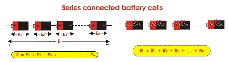
If E is the overall emf of the battery combined by n number cells and E1, E2, E3, …………… En is the EMFs of individual cells.
Similarly, if r1, r2, r3, …………… rn is the internal resistances of individual cells, then the internal resistance of the battery will be equal to the sum of the internal resistance of the individual cells i.e.
Parallel Batteries
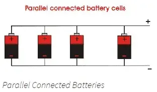
When positive terminals of all cells are connected and similarly negative terminals of these cells are connected in a battery, then the cells are said to be connected in parallel. These combinations are also referred to as parallel batteries. If the emf of each cell is identical, then the emf of the battery combined with n numbers of cells connected in parallel is equal to the emf of each cell. The resultant internal resistance of the combination is,
The current delivered by the battery is the sum of currents delivered by individual cells.
Mixed Grouping of Batteries or Series Parallel Batteries
As we said earlier, the cells in a battery can also be connected in a mixture of both series and parallel. These combinations are somesometimeserred as to eriseries-paralleltbatteriesload can require both voltage and currently more than that of an individual battery cell. For achieving the required load voltage, the desired numbers of battery cells can be combined in series and for achieving the required load current, desired numbers of these series combinations are connected in parallel. Let m, numbers of series, each containing n numbers of identical cells, are connected in parallel.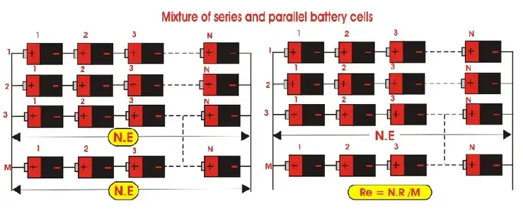
Again assume emf the of each cell is E and the internal resistance of each cell is r. As n numbers of cells are connected in each series, the emf of each series as well as the battery will be nE. The equivalent resistance of the series is no As, m number of series connected them in the parallel equivalent internal resistance of that series and parallel battery is nr/m.
3. Electrical connectors:
BUSBAR: In electric power distribution, a busbar (also bus bar) is a metallic strip or bar, typically housed inside switchgear, panel boards, and busway enclosure for local high current power distribution. They are also used to connect high-voltage equipment at electrical switchyards, and low-voltage equipment in battery banks. They are generally uninsulated and have sufficient stiffness to be supported in the air by insulated pillars. These features allow sufficient cooling of the conductors, and the ability to tap in at various points without creating a new joint.
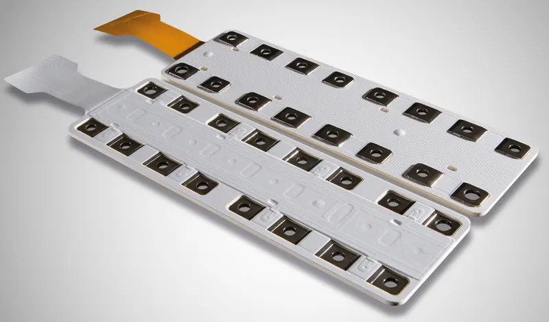
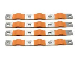
- These connections are typically done using ultrasonic bonding or laser welding. Busbar connections between modules can also be done mechanically using fasteners.
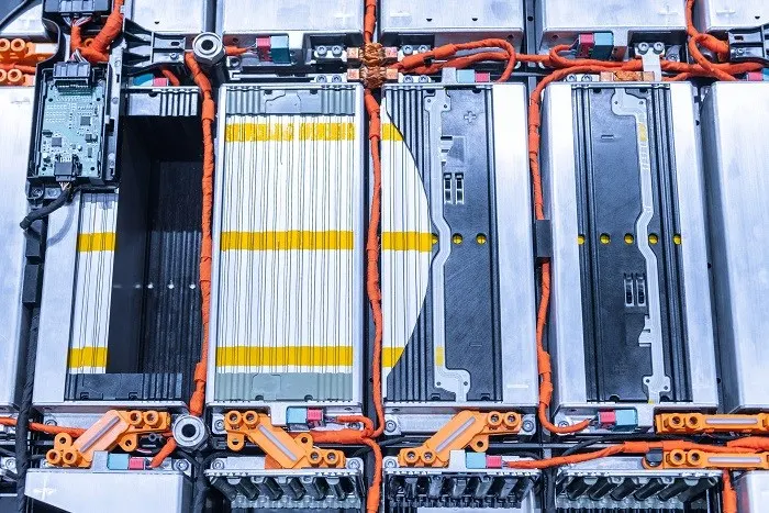
EV car battery pack and wiring (Image: Shutterstock):
ULTRASONIC BONDING:
How do Ultrasonic Welding Systems work?
Ultrasonic bonding, or ultrasonic welding, is an industrial welding process that uses ultrasonic vibrations to join plastics, metals, or dissimilar materials together. During welding, the joined materials are typically held together by a fixture (or anvil) and a sonotrode (a metal tool that vibrates).
When the sonotrode applies mechanical vibrations to the surfaces to be joined, the resulting friction generates heat. This heat typically joins the materials within 0.1 and 1 second.
Ultrasonic bonding is said to be a solid-state welding process because welding occurs below the material’s melting point. This is especially important for metal bonding applications where high temperatures could generate undesired properties.
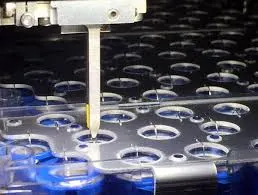

Ultrasonic bonding starts with the power supply, a small box that converts the incoming electrical current into a high-frequency, ultrasonic signal
This electrical energy travels to the converter (or transducer), which transforms it into mechanical vibrations through discs that vibrate very quickly. The size of these vibrations is called the “amplitude”, a key parameter when configuring ultrasonic welding systems.
Vibrations are then amplified in the booster and relayed to the welding horn (or sonotrode). This is the metal part that performs the welding by transferring the vibrations to the part surface. The horn is specifically designed to take the shape of the surface to be welded.
LASER WELDING:
Laser welding and laser cleaning are among the most promising technologies for EV battery welding. Lasers provide the speed and precision required for the thousands of welds in battery packs, battery modules, and cells. As a green technology, lasers are also in line with the objectives of the e-mobility industry.
Unlike alternatives, all types of battery cells can benefit from laser technology, including cylindrical cells, prismatic cells, and pouch cells. Laser welding and cleaning are being implemented for a wide range of electric vehicles:
|
|
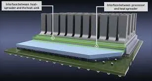
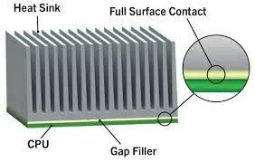
4. Thermal interface materials: such as pastes, adhesives, and gap fillers are inserted between battery components to join them mechanically while improving thermal properties between surfaces. With the rise of the structural battery pack, TIMs are becoming essential components.
GAP FILLERS
▪ Soft and compressible to relieve stress
▪ Ideal for applications with large gap tolerances, typically from 150 µm to 5 mm
17
Benefits
• Excellent mechanical aging
• Maintain low stress interfacial contact
• Non-flowable for thicker bond lines, highly thixotropic for fast processing
• Fast heat cure or room-temperature cure
Limitations
• Not for thin bond lines
• No chemical bonding, tack adhesion only
• Mixing: 2-part only
PASTES, PUTTIES, GELS, AND GREASES
Thermal pastes, putties, gels, and greases are produced in the fluid state at room temperature. They usually have a consistency that is like toothpaste or soft butter.
While some products are designed to harden or cure into a rubbery consistency after being applied, some will remain fluid throughout their entire working lives.
Grease is usually sold as a non-curing product and applied in thin layers to help with the thermal transfer between surfaces that are typically smooth and flat. Putty is a material that is applied to increase thicknesses. It is used for filling in gaps that are present between irregular or unusual surfaces or those that do not touch one another.
These products are electrically non-conductive. However, some can be designed to be conductive and may cause issues if the bridge nodes in the circuit shounot are connected.
Unfortunately, depending on the application, several issues may arise. In most cases, a better option is to use pads, tapes, adhesives,ives, or roll g o,o ds, as they eliminate many of the most common issues.
What Is Adhesive Bonding and Why Is It Important?
Adhesive bonding is a critical process for structural batteries. It is used to join surfaces together, creating a structure that distributes the stress load evenly, which provides more strength. It is done using structural adhesives, such as epoxy resin mixed with a hardener, adhesive tapes, or double-sided adhesive sheets.
Adhesives serve many purposes. By replacing mechanical fasteners, they reduce the battery’s weight and hence improve its range. Adhesives also protect the battery from environmental factors, such as water, dust, road salt, and automotive fluids. They improve the battery’s mechanical properties as well, offering protection against shocks and vibrations. Finally, they can act as thermal conductors or insulators, helping regulate the battery’s temperature for improved safety and durability.
5. Battery Management System (BMS):
Definition
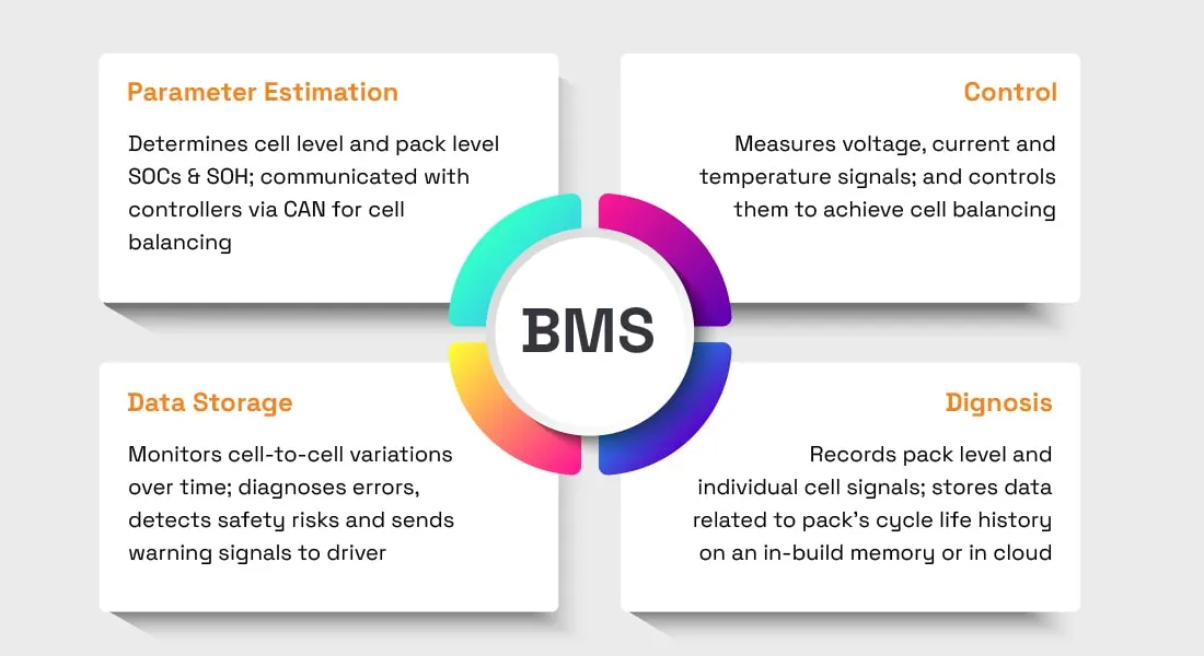
Battery management system (BMS) is technology dedicated to the oversight of a battery pack, which is an assembly of battery cells, electrically organized in a row x column matrix configuration to enable the delivery of a targeted range of voltage and current for a duration of time against expected load scenarios.
The oversight that a BMS provides usually includes:
- Monitoring the battery
- Providing battery protection
- Estimating the battery’s operational state
- Continually optimizing battery performance
- Reporting operational status to external devices
Here, the term “battery” implies the entire pack; however, the monitoring and control functions are specifically applied to individual cells, or groups of cells called modules in the overall battery pack assembly. Lithium-ion rechargeable cells have the highest energy density and are the standard choice for battery packs for many consumer products, from laptops to electric vehicles. While they perform superbly, they can be rather unforgiving if operated outside a generally tight safe operating area (SOA), with outcomes ranging from compromising the battery performance to outright dangerous consequences. The BMS certainly has a challenging job description, and its overall complexity and oversight outreach may span many disciplines such as electrical, digital, control, thermal, and hydraulic.
How do battery management systems work?
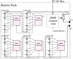
Battery management systems do not have a fixed or unique set of criteria that must be adopted. The technology design scope and implemented features generally correlate with:
- The costs, complexity, and size of the battery pack
- Application of the battery and any safety, lifespan, and warranty concerns
- Certification requirements from various government regulations where costs and penalties are paramount if inadequate functional safety measures are in place
There are many BMS design features, with battery pack protection management and capacity management being two essential features. We’ll discuss how these two features work here. Battery pack protection management has two key areas: electrical protection, which implies not allowing the battery to be damaged via usage outside its SOA, and thermal protection, which involves passive and/or active temperature control to maintain or bring the pack into its SOA.
6. Battery Thermal Management System (BTMS):
EV Battery Cooling Methods
EV batteries can be cooled using air cooling or liquid cooling. Liquid cooling is the method of choice to meet modern cooling requirements. Let’s go over both methods to understand the difference.
Air Cooling
Air cooling uses air to cool the battery and exists in passive and active forms.
Passive air cooling uses air from the outdoors from the cabin to cool or heat the battery. It is usually limited to a few hundred watts of heat dissipation.
Active air cooling gets its air intake from an air conditioner, which includes an evaporator and a heater to control the air’s temperature. It is usually limited to 1kW of cooling and can be used to cool or heat the cabin.
Liquid Cooling
Liquid cooling is the most popular cooling technology. It uses a liquid coolant such as water, a refrigerant, or ethylene glycol to cool the battery. The liquid goes through tubes, cold plates, or other components that surround the cells and carry heat to another location, such as a radiator or a heat exchanger. Components carrying the liquid prevent direct electrical contact between the cells and the liquid coolant.
Like air cooling, passive and active systems exist. Active liquid cooling is more complex and expensive but provides better performances such as propulsion and charging power. The difference between active and passive cooling is that passive cooling uses ambient air to control the liquid’s temperature, whereas
Some thermal management systems use a direct-contact medium such as oil or other dielectric liquids that are directly in contact with the cells. This is mostly used in non-consumer EVs, as they are less safe and provide less effective insulation between the cells and the surrounding environment.
Cooling Methods Over Time
Nowadays, most batteries are liquid-cooled using active cooling, as it allows better control over the temperature. Liquids are better heat conductors than air—hundreds of times better to be precise—which facilitates temperature management.
Because batteries were much more expensive to produce at the beginning of the EV revolution, manufacturers were doing everything to minimize production costs, which made passive air cooling more attractive. But battery costs have dropped over the last decade, and quick charging, which has more demanding cooling requirements, has gained in popularity. As a result, passive air-cooling technology has lost its popularity.
At the beginning of the 2010s for example, you had two options for about the same price: a Nissan Leaf with air cooling and a longer-range battery, or a Chevy Volt with active liquid cooling but a lower-range yet more powerful battery. A high-range, powerful battery that was actively cooled would have been too expensive at the time.
One of the reasons why active cooling is more expensive is that it includes more components, such as a heat pump, a heat exchanger, a circulating pump, valves, and multiple temperature sensors. However, the cooling results are much more reliable.
Why EV Batteries Need to Be Cooled
EV Batteries have specific operating changes, which are critical for the battery life and performance. They are designed to operate at ambient temperature, which is between 68°F and 77°F (20°C and 25°C). Better control over the battery temperature improves their performance and life.
- During operation, they can withstand temperature between -22°F and 140°F (-30°C and 50°C)
- During recharges, they can withstand temperatures between 32°F and 122°F (0°C and 50°C)
Batteries generate a lot of heat during operation and their temperature must be brought down within operating ranges. At high temperatures (between 158°F and 212°F, or 70°C and 100°C), thermal runaways can occur, causing a chain reaction that destroys the battery pack.
During fast charges, batteries must be cooled down. This is because the high current going into the battery produces excess heat that must be extracted to preserve the high charging rate and not overheat the battery.
They sometimes also need to be heated up when the temperature is too low or to boost reperformance for example, cells cannot be charged below 32°F (0°C). Or, companies like Tesla offer battery preheating in some models to reach high performances, going from 0 to 60 mph in less than 2 seconds.
Thermal Management Challenges
The most common thermal management challenges for EV batteries are leaks, corrosion, clogging, theme, and aging. As you will see, liquid cooling systems present challenges that are inexistent for air cooling systems.
- Leaks can only occur in liquid cooling systems, whose pipe connections have risks of leaks as the battery ages. Any leaks will rapidly degrade the batterybattery'smance and life. They can even cause the EV to stop operating if humidity attacks the battery’s electrical insulation. Battery modules, interconnections, pumps, and valves must all remain intact.
- Corrosion can only occur in liquid cooling systems, whose cold plates can corrode as the liquid glycol gets older. Therefore, the cooling liquid must be replaced as part of the vehicle’s maintenance.
- Clogging is a risk that is present in the hundreds of small channels where liquid travels in the battery.
- Climates around the globe pose different thermal challenges for batteries. Examples include leaving the car under heavy sun for a long time or living in a place where there are extremely low temperatures in winter. Batteries must be able to tolerate wide temperature ranges at all times. To achieve this, the battery cooling system must be active even when the vehicle is not in use.
- Aging causes thermal management problems that must be planned for. As batteries get older, a larger portion of the energy loses as heat. The thermal management system must be built for these tougher conditions that occur later in the battery life, not just for typical conditions during the first years.
Examples of Battery Thermal Management Systems
The following schemas show thermal management systems in well-known electric vehicles.
Nissan
Chevrolet Volt
7. Contactor System :
In a battery, the contactors are a switch that can be operated by the control system. They are essentially a relay. These contactors are designed to be able to break (switch off) the circuit under full load (maximum current and at maximum system voltage).
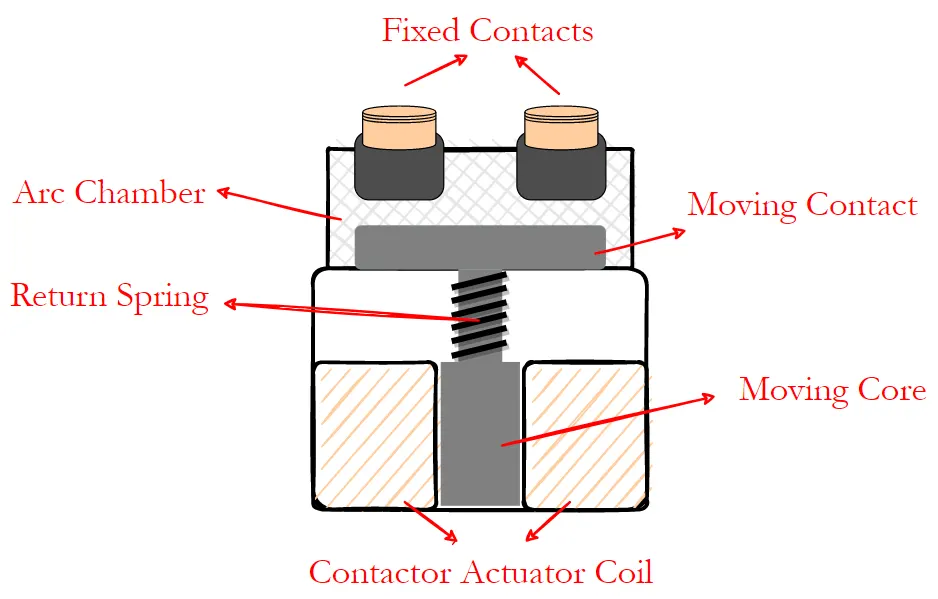
Introduction to Contactors :
There are two main types of contactors: Normally Open (NO) and Normally Closed (NC). A NO contactor does not allow current to flow when the actuation circuit is not powered. However, an NC contactor connects the external circuit when the contactor actuation coil is not energized. Therefore, we use EV contractors as NO to switch off the circuit in case of loss of actuation circuit supply.
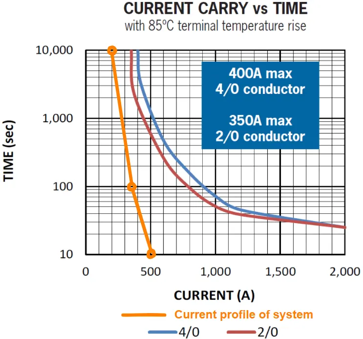
Contactor selection is an iterative process that includes consideration of system specifications as well as failure scenarios. Most of the contactor manufacturers share necessary information in datasheets. Thus, a wise approach would be to make a comparison table to cover basic specifications like thermal and mechanical initially.
8. Housing:
Structure of a Battery Housing;
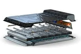
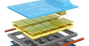
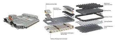
A battery housing consists of the actual stainless-steel housing, which creates the structural load capacity between the components, batteries, and control components in the interior. Lithium-ion batteries work optimally when they are operated in a temperature range between 18 and 25 °C. Maintaining this temperature range usually requires the use of a cooling system with a cooling plate. Additional functional and safety components in the housing are used for the various expansion levels. This includes materials that guarantee fire protection in case of a battery’s potential thermal runaway and which simultaneously protect the batteries in the interior against damaging external influences, such as high or low outside temperatures. In case a battery cell does catch fire, for example, due to a short circuit, it is extremely important to safely release the reaction gases using a pressure relief valve. This ensures the protection of nearby persons and their safe evacuation from the danger zone. When batteries are used in vehicles, there is the potential danger of a collision with other road users or fixed objects. If the sensitive battery cells are damaged by a collision, this usually causes the entire vehicle to catch fire. To avoid the effects of such accidents, a crash structure is an optimal solution for bracing the impact of forces from the outside so that they won’t affect the sensitive battery cells.
The battery housing must offer the largest possible space envelope for the battery modules while meeting requirements for sealing and mechanical loading. A geometrically simple battery housing can be designed using stainless steel as a deep-drawn shell. The advantage of this approach lies in its sealing and less elaborate manufacture compared to the use of fabricated structures made from low-alloyed steels or extruded aluminum profiles. Furthermore, deep-drawn battery floor shells save considerable packaging space. There is also no need for production steps involving welding in the battery “clean room”. This eliminates thermal distortion and reduces cleaning requirements, which lowers production costs. Figure 1 shows a diagram of all the battery housing components.
Figure 1. Stainless steel concept for an EV battery compartment.
Thermal management
Li-ion modules for EVs generate a significant amount of heat inside the sealed battery housing. In the event of damage, the liquid coolant must not come into direct contact with the modules. The ideal solution is passive cooling, which presents additional advantages in production and assembly, as well as subsequent accessibility. Temperatures above 45 °C can cause battery damage. Equally, charging capacity and vehicle range decrease at temperatures below −5 °C, so indirect system heating might be needed in winter. Functional thermal management guarantees high battery performance. This is enhanced by a stainless-steel sheet that offers thermal advantages over extruded profile and die-cast semi-finished products.
Figure 2 illustrates the principle of a dual-wall shell, where the inner shell contains the battery modules and the outer shell the cooling and/or heating circuit. Using an inner shell made from thin ferritic stainless steel and a thicker outer shell made from austenitic stainless steel takes advantage of the different material properties.
Figure 2. Dual-wall shell concept with integrated thermal management.
Crash frame
High energy absorption is the key property of the crash frame, which is positioned between the battery shell and rocker panels. This configuration must form a coordinated system in the event of a side impact. Alongside geometric design, material selection is a crucial factor. In addition to high residual ductility, the component must have very high strength.
Using Forta H-Series with its TWIP (Twinning Induced Plasticity) strengthening mechanism, it is possible to produce complex shapes as roll-formed profiles, with high stiffness due to the complexity of their form. The forming energy applied also causes significant material hardening, resulting in extremely high strength.
The ideal scenario is a twin chamber, with the profile facing the rocker panel absorbing the energy and the inside profile generating high intrusion resistance.
Figure 3. Crash frame in a form of a high-strength pillow-plate absorber.
An alternative crash frame concept is internal high-pressure forming using an active fluid medium for producing extremely stiff pillow-plate absorbers, see Figure 3. Again, the deformation energy of the process produces significant material hardening, while the geometry delivers high stiffness. Just like the two-chamber principle, an outward-facing energy-absorption area can be defined using a section of a thin exterior sheet. The space between the two areas can be used for other applications such as the thermal management system.
Under-ride protection
The under-ride guard supplements the battery housing to protect the thermal management system and modules against intrusion from the underfloor area. It requires a careful balance of energy absorption capacity and high resistance to intrusion. Stiffness is a vital issue, which can be positively influenced by corrugations. This area is also subject to high corrosive load so stainless steel is particularly beneficial.
One approach is to use mechanical compression springs, cold-formed from stainless steel, embedded in a double floor, as shown in Figure 4. This construction method causes the underfloor guard to glance off, reducing impact forces. Also, other stainless steel systems following the behaviour of springs could be used beneficially – such as corrugated sheet metals or bend-formed structures.
Figure 4. Schematic view of the double-floor spring design.
9. Communications System :
What is a CAN Bus?
CAN Bus, which is short for Controller Area Network Bus, is a communication-based bus system designed to facilitate data transmission and communication between devices and microcontrollers independent of a host computer. Simply put, it is a message-based protocol that allows various smaller systems within a vehicle to communicate without physical connections or wiring.
The CAN bus can be designed to handle a wide range of microcontrollers and devices in such a dynamic way that during active data transfer, the device with the highest-rated priority is allowed to transmit data first while the others are transmitted sequentially.
A CAN Bus is a preferable option used by vehicle engineers for several reasons. One such reason is that a CAN Bus communicates data in real-time, is highly reliable, and is very effective in data transfer.
What is a CAN Open System?
CAN Bus is a dynamic communications systems protocol that has many sub-protocols based on it, one major protocol is CAN Open.
CANopen is an application protocol based on a CAN Bus system that effectively allows CAN protocol to apply to a wide variety of applications. It is currently one of the most standard communication sub-protocols used by engineers for different applications in electric vehicles and other machines.