Project 1 Mechanical design of battery pack
AIM:- To devlope a battery pack capacity of 18kwh using ANR26650M1-B drawing alone with there Mechanical design.
Solution#:-
ANR26650M1-B :-
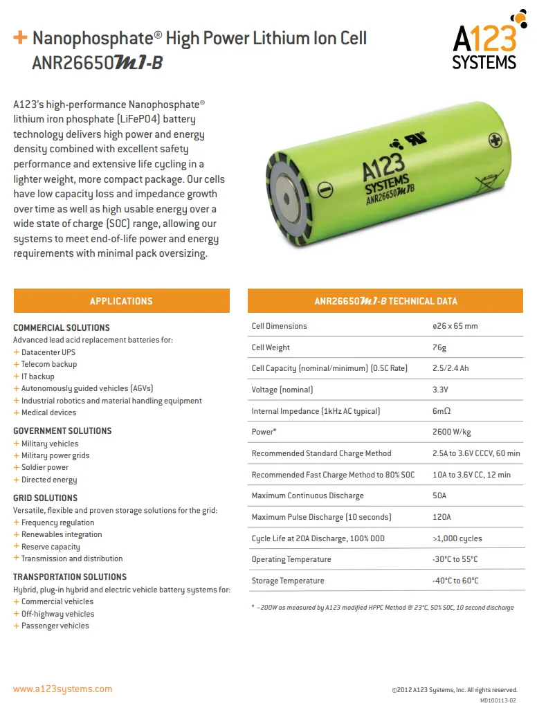
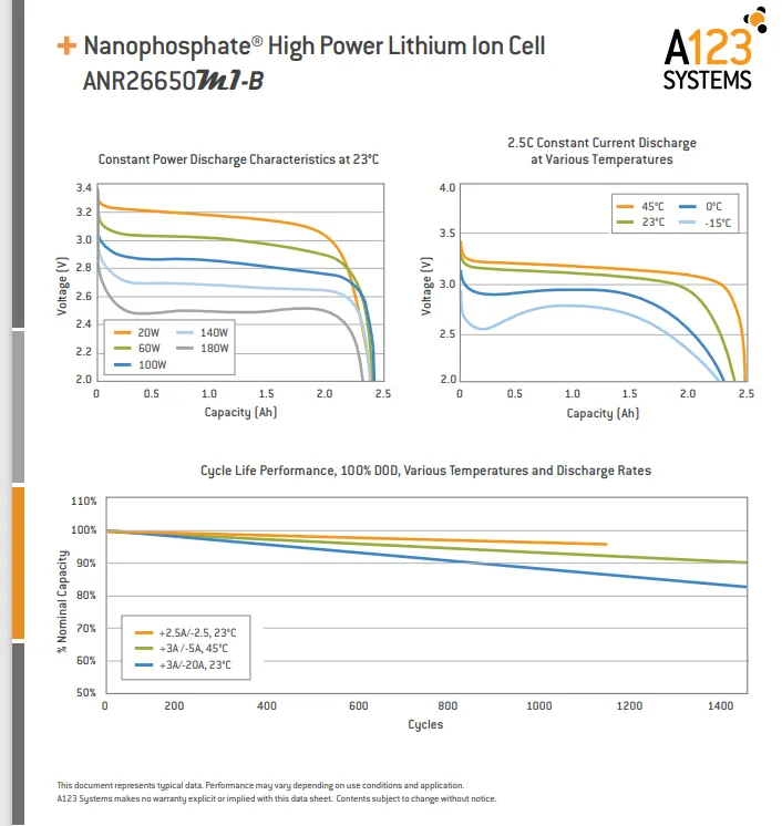
Cell Dimensions:-
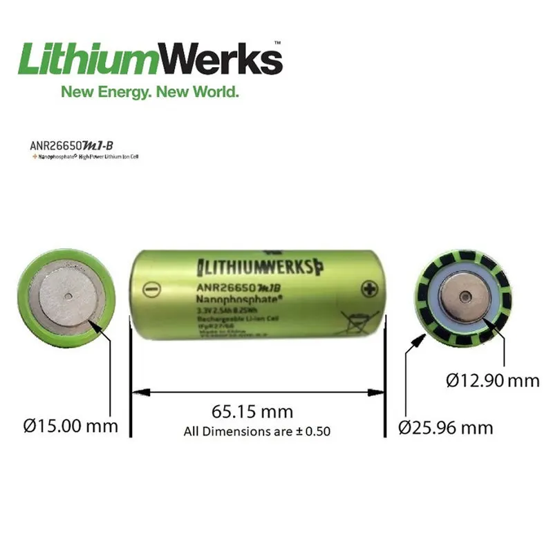
Calculation :
This calculation is to determine how much space of volume the cell will take in the capacity of 18kw.
Cell energy:- Nominal voltage* Nominal capacity
=2.5Ah*3.3V
= 8.25Wh
Cyclinderical cell volume:- `pir^2h`
= 3.14*0.013*0.013*0.065
= 0.0344929 m^3
So now we have to calculate how much Watt per volume the cell can produce:
Cell energy density:- Cell energy / Cylinderival cell volume
= 8.25 / 0.0344929
= 239.17 Wh/m^3
Now we have to assume the battery pack:
To get 18 kw as a output power we have to conside serises and paraller cells to be connected to create the battery pack module of the required capacity.
let us consider 58 cells connected in series a and 38 cells connected in parallel.
- So the toatal number of cells required =58*38=2204 cells
Voltage of the pack:- Nominal voltage*No. of cell in series
= 3.3*58
=191.4
Current of the pack:- Cell capacity * No. of cell in parallel
= 2.5*38
=95 Ah
The total energy of the battery pack:- Voltage of the pack*current of the pack
=191.4*95
=18183 W
=18.18KW
Now we know the total number of cells which are required in the battery pack we can now calaculate the energy density,volume and weight of the enitre batery pack.
Total volume =Cell volume*Total no of cells
=0.0344929*2204
=76.022m^3
And
total weight of the battery=Total no of cells*Weight of each cell
=2204*0.076 kg
=167.504 Kg is the total weight of the battery
- Now we know the weight and volume of the battery pack of 18kw .So, we will consturct the battery pack.
Battery Pack:
- A battery consists of one or more electrochemical cells (battery cells) which are converting chemical energy into electrical energy (during discharging) and electrical energy into chemical energy (during charging).
- The type of elements contained within a battery and the chemical reactions during discharging-charging events define the chemistry of a battery.A battery cell consists of five major components: electrodes – anode and cathode, separators, terminals, electrolyte and a case or enclosure
- Individual battery cells are grouped together into a single mechanical and electrical unit called a battery module.
- The modules are electrically connected to form a battery pack.
- There are several types of batteries (chemistry) used in hybrid and electric vehicle propulsion systems but we are going to consider only Lithium-ion cells. The main reason is that Li-ion batteries have higher specific energy [Wh/kg] and specific power [W/kg] compared with other types.
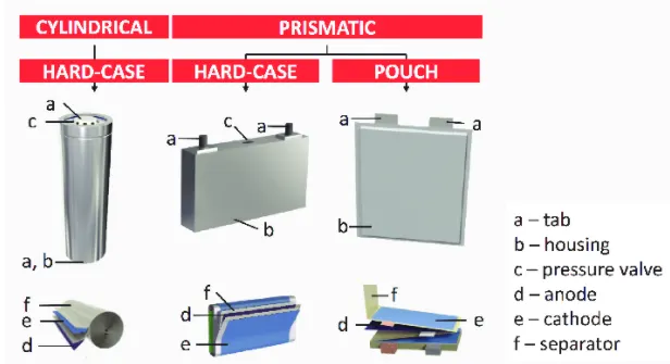
Ev uses mainly 3 types of cells:Cylindrical,prismatic and pouch.
Battery Pack construction:
Cells in Parallel, the P-Count
[In this article, I will use a small rectangle-shaped pack as an example, which is the easiest style to understand when learning these principles. Once you have a firm grasp of this, you can easily scale your pack up to different shapes and sizes]
If you take several cells and connect their same-type electrodes in parallel, they all will act as though they are one large cell. Also, when you first connect them to each other, they MUST be at the same level of charge [The positive electrode is the Cathode, and the negative electrode is the Anode. In the pics below, the positive is a red plus sign, the negative is a black dash].
By that I mean…if you connect a fully charged cell “in parallel” to a cell that is low, the high cell will try to charge up the low cell in just a few seconds, since there is no built-in resistance between them across the connecting bus to slow things down. A rapid equalization will absolutely cause both of them to get VERY hot. Permanent damage is the least that will happen, and most likely one of them (or both) will go up in flames. However, if there is only a tenth of a volt in difference between them, that would not be a problem (for instance, from 4.1V to 4.2V would be OK, they would both equalize at 4.15V).
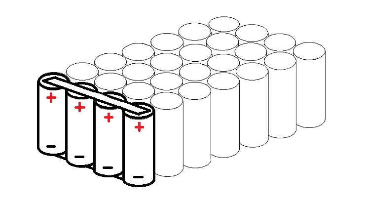
Four cells in parallel in a 7S/4P pack (28 cells). There is a full-length electrically-connecting metal strip (bus) on the top and the bottom of these four cells. The four cells in parallel can be configured in any shape, but having them in a straight line is the easiest introduction to understanding it.
The P-count determines the capacity of the pack in Amp-hours (Ah), and it also determines the amount of current the pack will be able to produce, measured in amps. For this example, we will use my favorite ebike cell, the Samsung 30Q. It is factory-rated as having 3000-mAh (milli-Amp-hours), which is the same as 3-Amp-hours (3-Ah). If you have four in Parallel, the finished pack can be rated as 12-Ah’s worth of range (4P X 3-Ah = 12-Ah).
Now we come to the amount of power that the pack can safely put out. The 30Q is a hot-rod cell (along with the HG2 and the 25R), and it is factory rated at 15-Amps continuous. However, almost all cell models get hot if you actually run them continuously at their listed rating. I recommend that nobody should ever let their pack get hotter than 140F (60C) under any conditions. Doing that will lead to a very short pack life.
Fortunately, ebikes usually only draw their peak amps for a few seconds while accelerating. Once you reach a cruise phase, the continuous amps that the controller and motor will draw is MUCH lower when you are simply maintaining your speed. If we use the 15A figure as our designed max amps, the pack will just get a little warm, and that means it will last a very long time. Four 30Q cells in parallel that are rated for 15A means we can depend on getting 60A from this pack without damage (4P X 15A = 60A).
Cells in Series, the S-count
When you connect cells together in series, it doesn’t change the amps or the capacity, it only raises the voltage of the pack. Hooking them up in series means that you connect the positive end of one cell (or P-group) to the negative end of the other.
For the cylindrical 18650-format cells that are the most popular (18mm in diameter, 65mm long), they use the lithium-NCA or lithium-NCM chemistry (the cathode uses Nickel-Cobalt-Aluminum…or…Nickel-Cobalt-Manganese). Those chemistries have a nominal (average) voltage of 3.7V…and in order to get the longest possible life from the pack, use 3.3V per series-cell as the Low-Voltage-Cutoff (LVC), and 4.1V as the fully-charged target.
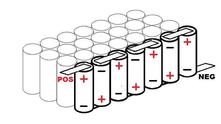
Seven cells in series in a 7S/4P pack, which is a nominal 24V. This is 28.7V when fully charged to 4.1V per cell.
The common max charge is 4.2V per cell, but when cells rest (for any length of time) at that high of a voltage, it will significantly degrade their life. Charge the pack to 4.1V times the series number.
The BMS, how to connect it?
The BMS is the Battery Management System. It performs several functions. The two fat wires (red and black) from the charger will “bulk charge” the pack until it gets very close to being full, and then the charger will switch over to using a very low charge rate as it gets closer to being full. A 3A or 5A (continuous) charge rate is very common for the bulk charge.
This charging profile is called CC/CV, for Constant Current / Constant Voltage. It’s a simple and inexpensive way to accomplish a subtle goal.
We all want an affordable battery pack, so…we buy mass-produced cells. This means that there will always be very minor differences in the internal resistances of each cell. To use the example of our theoretical 7S/4P pack above…each 4P cell-group is “seen” by the charger and controller as one large cell. The parallel connecting metal strip ensures that they all constantly equalize to each other, so we must discuss them as if they were in fact, one large cell.
There are seven of these “in series” to get 24V. Now, we then set our dumb bulk DC power-supply as a charger to 3A (with NO BMS), and we use (7S X 4.1V =) 28.7V as our fully-charged goal. It works like a dream. However, only five of the P-Groups are actually at 4.1V. One P-group is at 3.9V due to high internal resistance, and another P-Group is at 4.3V due to low internal resistance. Since our dumb charger only reads the 28.7V of the assembled pack when it shuts off, it has no idea of the trouble that is brewing…
High-resistance cells run hotter than an “average-resistance” cell, but for this discussion, let’s just assume that it never gets “too hot” to cause trouble (over 140F / 60C). Also…cells located at the heart of a pack run hotter than cells at the edge, since the edge-located cells shed “some” heat to the outside shell of the pack.
That leaves the low-resistance cell to consider. It will dump amps faster than the other cells (when accelerating), and it will also gulp the charge faster, too. It will actually run cooler than the other “average resistance” cells, but…a bulk charger will overcharge it. If letting a pack sit overnight at 4.2V per cell will cut its life in half (compared to 4.1V per cell), then…what will letting one cell sit overnight at 4.3V do? It will lose capacity rapidly.
And that means that, the one bad cell will cause the entire P-group to experience voltage-sag near the end of a ride, and then…that one low P-group will cause the entire pack to experience voltage-sag. And this means that…for a split second on acceleration, the LVC will “think” that the entire pack is too low, and it will cut off ALL power in order to “save” the pack (one of its most important jobs).
The pack will still “work”, but…your accelerating days are over. You may have planned on buying a new pack in three years (or more), but because of one “slightly” bad cell, the entire pack is now useless to you after only a few months. This is why the bulk-charge phase (CC/Constant Current) only takes the pack to about 4.0V per cell. For the rest of the topping-charge, the Constant Voltage / CV phase is accomplished at low amps, with some sensitive electronics thrown in…
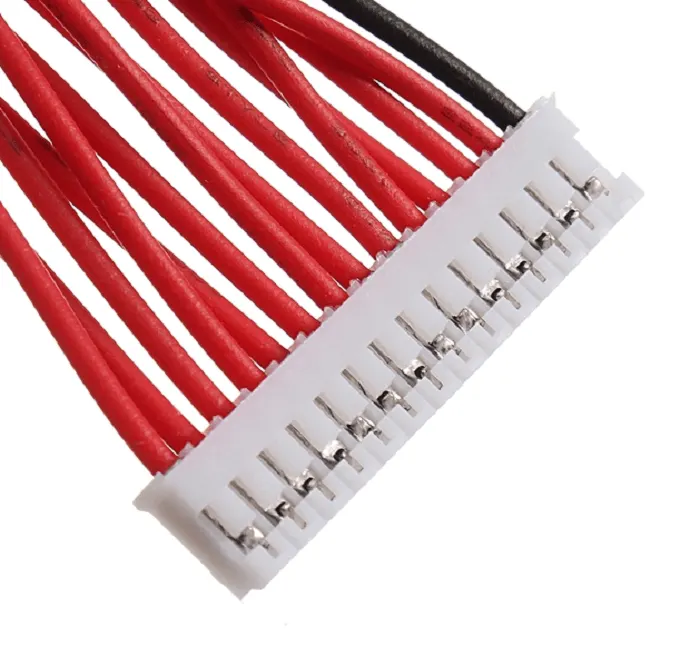
A BMS harness. The 14 wires identify this as being made for a 13S pack, which is 48V. Notice that one wire is black (or at the very least, a different color from the rest). Some BMS harnesses have a different color for each P-group, but…this will actually work fine, if you follow the common pattern.
There is one crazy “voodoo electronics” feature of a BMS. The quantity of small balancing wires is going to be…the “series number plus one”. So, our theoretical 7S pack will use eight balancing wires. This just sounds nuts. Everyone who starts learning about batteries KNOWS that there are two poles (to each cell, or P-group). The red positive, and the black negative. You would think that to balance the charge at low amps during the final CV phase of the charge…you would need 14 wires instead of eight, when making minor adjustments to the seven P-groups (remember, each entire P-group will act like one large cell).
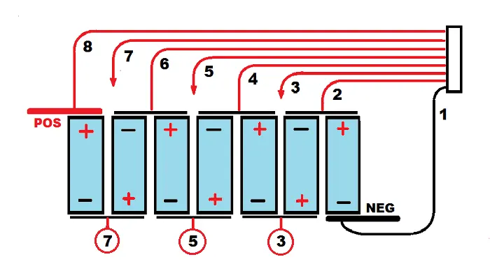
A basic BMS wiring scheme for a 7S pack. Once you understand the pattern, you can expand this to any size of pack.
Look carefully at the pic above. The white plug connects the dumb harness to the smart BMS. You can see that for the BMS to access the positive and negative ends of the first cell (and the connected first P-group), it uses the number-1 and number-2 wire. However, when moving on the the second cell?…the BMS uses the #2 and #3 wires. The number two wire is sometimes used as the positive to the number-1 cell, and sometimes used as the negative to the number-2 cell (and “so on” down the line, until you reach all of the P-groups in the series string).
This eliminates 45% of the possible BMS harness wires, but..it also makes the proper connection locations confusing for new builders. Even if you are still a little confused, just follow the BMS instructions carefully.
Side note: If your battery pack dies suddenly for no obvious reason, it is usually from some component in the BMS failing, leading to a complete drain of the pack down to zero-volts, or…a gross overcharge above 4.2V. This is why they are sometimes called a Battery-Murder-Suspect.
Other chemistry options?
The common NCA/NCM chemistries provide the best balance between capacity in a small package, and a useful amount of amps. However, there are other chemistries that might be an option for certain applications. The NCA/NCM “nominal” voltage is widely regarded as being 3.7V per cell, and…for the max possible life, I’d use 3.3V per cell as the LVC and 4.1V as the full charge.
LiFePO4 / LFP is commonly called “Iron Phosphate”, and it has a nominal voltage of 3.2V per cell. That means that it takes 16 LiFePO4 cells to make a 48V pack, and NCA/NCM only require 13 cells for 48V. However, LiFePO4 is considered the most fire-safe (sometimes found as a starter battery on small aircraft), and they also typically last about twice as long as the common NCA/NCM 18650-cell packs.
A 4S pack of LFP is the most common replacement for a 12V Lead-Acid battery pack (4P X 3.2V = 12.8V nominal).
That being said, NCA/NCM in the 18650-format cells have a much better selection of choices, and provide high power and long range in a small package that is affordable, due to mass-production. LFP can be found in flat pouch cells, 26650’s (26mm X 65mm), and large cylindrical 38120 cells (huge! 38mm X 120mm, from Headway, see below). I have actually found LiFePO4 in the 18650-format, but…the capacity was VERY low.
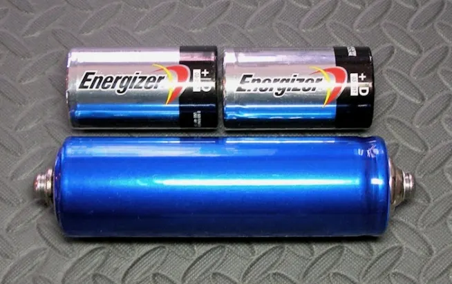
Headway LFP cells have threaded ends which make assembly into a pack very easy. However, the smallest one is roughly the size of two disposable D-cells.
One more obscure chemistry is Lithium-Titanate-Oxide (LTO). It has an even lower nominal voltage of 2.4V per cell. It may last ten times longer than NCA/NCM, and it also works well in very cold weather (along with providing high current). However, I have only found them in flat pouch cells, and they are hard to find, expensive, and have few size options.
The NCA/NCM chemistries can also be found in the slightly larger cylindrical 21700-format cells. These were developed by Panasonic in partnership with Tesla electric automobiles. However, they are currently expensive, and the majority of the factory production is going into the Tesla Model-3, and also the powerwalls (a home power back-up system).
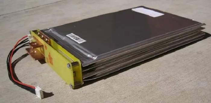
Here are four flat LFP pouch cells in series (4S). While 18650-format cells have a steel cylinder around them to provide compression and physical protection, pouch cells will need to have those added when building a pack. (notice the BMS harness has four black wires and one red). 3.2V X 4S = 12.8V nominal, for replacing a 12V lead-acid battery.
There ARE options, but…after any depth of research, almost every ebiker comes back to the 18650-format cells in the NCA or NCM chemistries.
Honeycombs are Sweet
In the pack example above (7S / 4P), the cells are aligned in straight rows and columns, which I might refer to as “rank and file” (like soldiers marching). However, the next most popular arrangement is to nest the cells of one row into the valleys of the next, in what many have come to refer to as… a honeycomb layout. I like it, but there are benefits and drawbacks to every option.
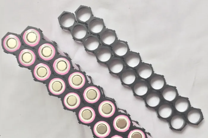
Here are plastic end caps that help space the cells in a honeycomb arrangement.
Using a honeycomb layout is mathematically the most compact way to arrange cells. That being said, the common rank-and-file arrangement leaves “just enough” space between four adjacent cells to allow a thin bolt to pass through from one side plate to the other (as seen below), and a honeycomb does not.
The plastic end-cap cell holders are an important safety feature for a DIY pack. The common square layout usually positions the cells so that they are almost touching each other. That means there will be almost no air-circulation, and that leads to the cells in the center of the pack to gradually run warmer by the end of a ride.
If you have a large enough pack, and the cells can provide lots of current, then…a low-current ride will not even get them warm. At the other end of the scale, a small pack of low-current cells that are being hammered on a ride will definitely get hot. The hottest spot will always be the positive cathode tips on the cells in the center of the pack.
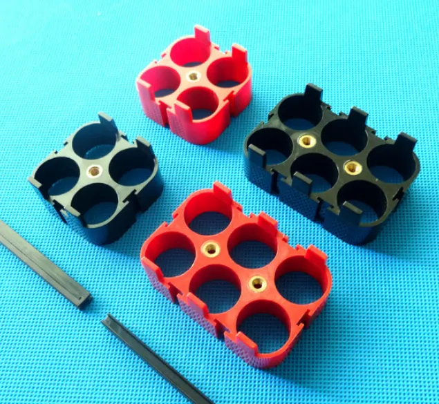
Plastic 18650 assembly caps from Ann Power. The threaded brass inserts are open all the way through. Bolts to hold both ends together can be ordered in plastic, if the common steel bolt material is a concern.
In the pic below, you can see that when using a honeycomb pattern, the side angle of the stacked cells is about 30-degrees away from the 90-degree corners in a common rectangular pack. This makes it a natural fit into the lower part of the frame triangle space. Mounting the weight of a pack low and in the center of the frame is the best place to put them, so the bike will handle well.

This pic is from a battery pack design website in Russia, and it helps you figure out how many cells can fit in your frame
The Russian battery pack configurator program can be found here. Feel free to experiment with every possible setting to see what the setting widows do.
Triangle packs, and odd shapes
The easiest pack to design is a rectangle (as seen above). However, like the pic below, it’s sometimes useful to make your pack a triangle, or some other odd shape. In the pic below, the builder is trying out a dry-fit to see how the 100 cells shown would work, and also how to arrange the 5P paralleled groups which are now in odd-shaped clusters (instead of being in-line).
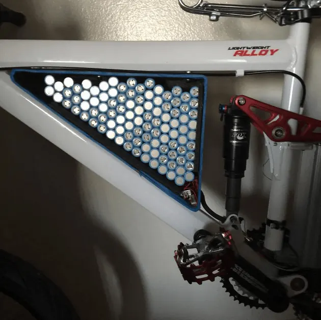
This is what 100 cells in the 18650-format look like in a bike frame triangle. This particular pack will be 20S / 5P.
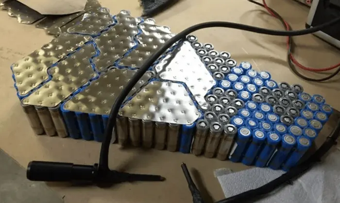
Instead of using nickel ribbon to make the series and parallel connections, you can use a flat plate to accomplish all of the electrical bus functions. This 21S pack has 12P groups, for a HUGE 252-cell pack.
Conclusion:Thus we have studied how to model a battery pack for 18kw battery.