Project 1 Mechanical design of battery pack
MECHANICAL DESIGN OF BATTERY PACK
BATTERY PACK:
A battery pack is a set of any number of (preferably) identical batteries or individual battery cells. They may be configured in a series, parallel or a mixture of both to deliver the desired voltage, capacity, or power density.
CELL:
A cell refers to a single anode and cathode separated by electrolyte used to produce a voltage and current. A battery can be made up of one or more cells.
CELL CONFIGURATION:
We have selected ANR26650M1-B 26650 Lithium Ion Power cell for designing the battery pack.
Nanophosphate® High Power LithiumIon Cell
ANR26650M1-B
A123’s high-performance Nanophosphate® lithium iron phosphate (LiFePO4) battery technology delivers high power and energy density combined with excellent safety performance and extensive life cycling in a lighter weight, more compact package. Our cells have low capacity loss and impedance growth over time as well as high usable energy over a wide state of charge (SOC) range, allowing our systems to meet end-of-life power and energy requirements with minimal pack oversizing.
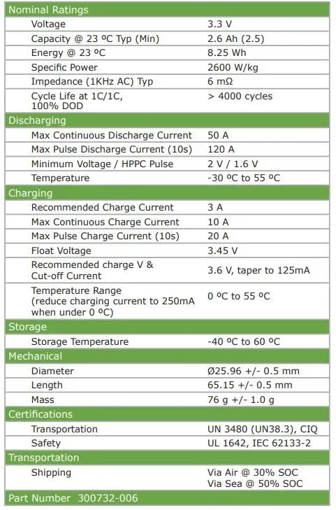
A123’s ANR26650M1-B CELL DATASHEET:
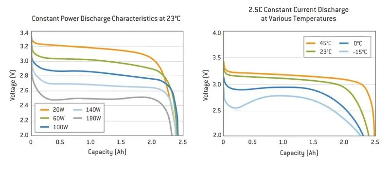
Constant power discharge characteristics at ambient temperature and constant current discharge characteristics at various temperatures:
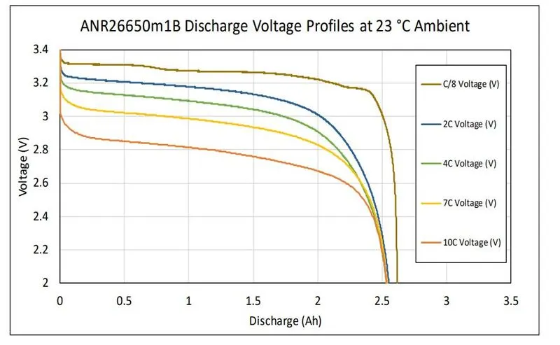
Discharge voltage characteristics at ambient profiles:
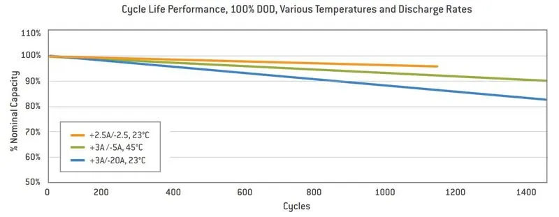
Cycle life performance :
Given data:
Battery pack capacity: 18 kWh
Cell: ANR26650M1-B
Assumptions:
Let us assume 350 V voltage is required to run the propulsion and auxillary units of electric vehicle.
Range we can assume 250km for the given battery capacity.
Mechanical design and calculation of battery pack:
Specifications of the cell ANR26650M1B :
Nominal Ratings
Voltage - 3.3 V
Capacity @ 23 ºC Typ (Min) - 2.6 Ah (2.5)
Energy @ 23 ºC - 8.25 Wh
Specific Power - 2600 W/kg
Impedance (1KHz AC) Typ - 6 mΩ
Cycle Life at 1C/1C, 100% DOD - > 4000 cycle
Calculation of Energy consumption:
Range = Capacity/Energy consumption per km
Energy consumption per km = Capacity/Range of vehicle
= 18000 wh/250 km
= 72 wh/km
Therefore as per our assumptions of 250km range for 18kwh battery pack capacity the energy consumption of vehicle is 72wh/km which is 0.072kwh/km.
We can also calculate the energy consumption using the WLTC driving cycle if we know the vehicle power and weight.
WLTC drive cycle
The average energy consumption of the vehicle Eavg [Wh/km] will be calculated on a homologation cycle. The test procedure WLTP (Worldwide harmonized Light vehicles Test Procedure) contains several driving cycles:
- Class 1 – low power vehicles with PWr<= 22
- Class 2 – vehicles with 22 < PWr<= 34
- Class 3 – high-power vehicles with PWr> 34
Where PWr [kW/Tonne] is the power-to-weight ratio, defined as the ratio between the rated engine power and kerb weight.
PWr=Pmax/mv
Here our battery pack is designed for Class 1 – low power vehicles.
Calculation of No. of cells:
Total no of cells:
Here, single cell voltage is 3.3V and a capacity of 2.5Ah. Energy provided from single cell is give 8.25Wh.
Total energy = 18000 Wh (as per battery pack)
Number of cells (N) = Total energy / (Nominal voltage*capacity)
= 18000 / (3.3*2.5)
= 2181.8
Total no of cells = 2182 no of cells
No. of cells in series:
The required voltage is 350V, the nominal voltage of the cell is 3.3V so to attain the required voltage the no of cells are connected in series to increase the voltage.
Total voltage of battery pack = Nominal voltage of cell * No.of cells in series
No. of cells in series = Total voltage of battery pack / Nominal voltage of cell
= 350V/3.3V
= 106.06
No. of cells in series = 106 nos.
No. of cells in parallel:
The given battery pack capacity is 18 kwh, now we have 106 number of cells connected in series but when connected in series it will increase only the voltage the capacity will be the same 2.5 Ah.
To get the complete battery pack capacity 18 kwh, we need to add the cells in parallel to increase and attain the battery capacity.
No of cells in parallel = Total no of cells / No. of cells in series
= 2181 / 106
= 20.58
No of cells in parallel = 21 cells in parallel
Or
Single module energy = ( no of cells in series * cell energy)
= (106 * 8.25)
Single module energy = 874.5 wh
how many similar modules should be connected in parallel to achieve 18KWh battery pack.
No of modules in parallel = 18000 Wh / 874.5 Wh
=20.58
No of modules in parallel = 21
So as per calculations 21 no of cells are connected in parallel
Amp hour capacity of battery pack:
21 no of cells are connected in parallel, therefore the capacity of battery pack is
Total Amp hour capacity = No of cells in parallel x Ah of single cell
= 21 x 2.5Ah
Total capacity of battery pack = 52.5 Ah.
Current Supplied:
Battery pack can provide 52.5 A of current continuously for one hour for discharge fully.
Cell configuration:
The cell configuration we arrived is 106S21P
106 no of cells in series and 21 no of cells in parallel
Total no of cells = 106 x 21 = 2226 Nos.
Total energy capacity after calculation:
Total energy = Total no of cells * energy of single cell
Total energy = 2226 * 8.25 = 18364.5 Wh
Total energy we are getting( 18364.5 Wh )is more than the given capacity (18000 Wh).
Battery pack configuration:
As per the calculation, the final configuration of our battery pack is
18.3 Kwh, 52.5 Ah, 106S21P
Cell volume:
The volume of each cell is calculated as:
- cylindrical cells, Vcc[m3]
Vcc=πr^2 H
Vcc = (πD^2/4) x H
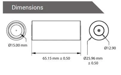
D – Diameter of cell – 25.96mm
H – height of the cell – 65.15mm
V = (π x 25.96^2 / 4) x 65.15
V = 3.45 x10^-5 m^3
The battery cell energy Ebc [Wh] is calculated as:
Ebc= battery cell capacity x battery cell voltage
= 2.5 x 3.3
Ebc= 8.25 Wh
volumetric energy density, uV [Wh/L]
uV=Ebc / Vcc(pc)
= (8.25/3.45x10^-5)x1000
uv = 239.130 Wh/L
gravimetric energy density, uG [Wh/kg]
uG=Ebc/mbc
= 8.25/0.076
uG = 108.55 Wh/kg
mbc = battery cell mass
battery pack mass (cells only) mbp [kg]
total number of cells Ncb
mass of each battery cell mbc [kg].
mbp =Ncb*mbc
= 2226 x 0.076 kg
battery pack mass (mbp) = 169.176 Kg
volume of the battery pack (cells only) Vbp [m3]
total number of cells Ncb
Volume of each battery cell Vcc(pc) [m3]
Vbp =Ncb x Vcc(pc)
= 2226 x 3.45x10^-5
volume of the battery pack (Vbp) = 0.0767 m^3
Dimensions of Battery pack Enclosure:
Dimension of cell:
Battery pack dimension:
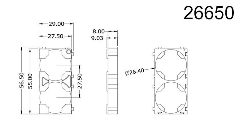
Lets select the standard battery holder dimension of 26650 battery cell
Length of the battery pack:
106 cell are connected in series,based on our selected cell holder 2 cells can be placed in holder and 53 such holders are connected to kept 106 cells.
length of battery pack (L) = (106/2) x length of holder
= 53 x 55 mm
L = 2915 mm
Breadth of battery pack:
21 cells are connected in paralle,based on our cell holder dimension,the width is 27.5mm for single holder
Width of battery pack (W) = 21 x width of single holder
= 21 x 27.5
W = 577.5 mm + space for wrapping,insulation,cover(15mm)
W = 592 mm
Height of battery pack:
Height of single cell is 65.15 mm
Total height of the battery pack = 65.15 + space for wrapping,insulation,cover,strip(15mm)
H = 100 mm
Volume of battery pack:
LxWxH = 2930x592x100 = 0.1735 m^3
Weight of battery pack:
Cell weight = 76g
Battery pack weight (BPw) = (cell weight x no of cells ) + weigth of cover and accessories
= (0.076 x 2226) + 6 kg
BPw = 175 kg
As per our considerations, the LxWxH = 2930x592x100 mm dimensions are need to place the battery pack in the vehicle cabinet. We can separate into no of modules to construct battery pack and place it in the cabinet. For example we can create 2 modules of (106/2 = 53)53 cells in series in one module.
Summary of battery pack mechanical design:
| Manufacturer | A123-Systems |
| Type | cylindrical |
| Model | ANR26650m1-B |
| Energy [Wh] | 8.25 |
| Volume [l] | 0.034510 |
| Energy density gravimetric [Wh/kg] |
108.55 |
| Energy density volumetric [Wh/l] |
239.06 |
| Total energy [Wh] | 18364.5 |
| pack configuration | 106S21P |
| capacity of battery pack [Ah] | 52.5 |
| LxWxH of battery pack | 2930x592x100 mm |
| Weight of battery pack |
175 kg |
| Volume of battery pack |
0.1735 m^3 |
Battery pack construction methods:
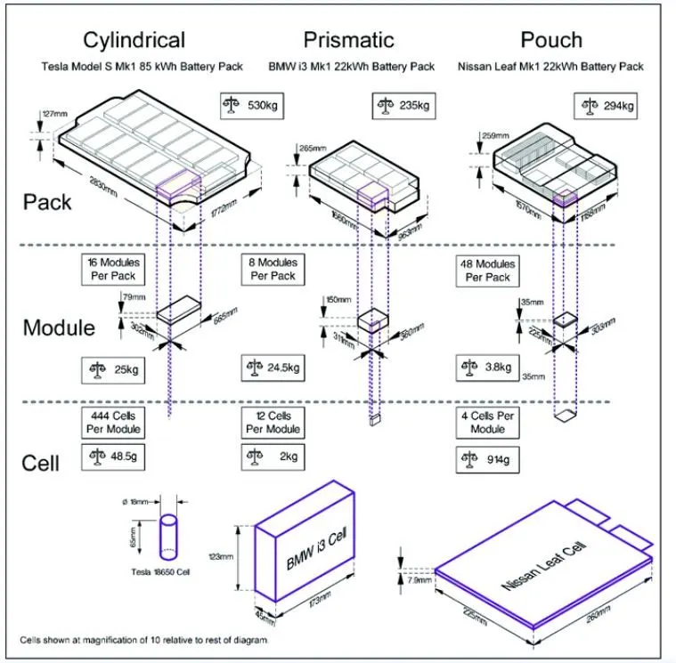
A ‘unit’ is a group of two or more battery cells joined together.A ‘module’ is formed by connecting multiple cells or units. As an independent operable battery unit, the module is installed with various sensors such as voltage and temperature sensors, safety components, and power and heat management electronics. Modules could be varied with their sizes, based on how they are allocated in the battery pack. A ‘pack’ is the final structure of the automotive battery that will be directly installed in the BEVs.
The Components of a Battery Pack
A battery pack is the most expensive part in an electric vehicle. It is a complex system made of a wide range of components. Here are some of the important components.
- Cells are the most important components of a battery pack. The mixture of materials comprising the cell is known as its chemistry. Different battery chemistries can achieve different performances and specifications. There are two common types of cells: energy cells and power cells. There are also many variants to provide the perfect trade-off depending on the application. In the EV industry, the lithium-ion cell (li-ion cell) is the most common chemistry. Alternative chemistries are sometimes used, such as Nickel-Metal Hydride (NiMH), which offers a slightly better lifecycle.
- Electrical connectors such as busbars, wires, or other distribution conductors are used to make series or parallel connections between cells and groups of cells. These connections are typically done using ultrasonic bonding or laser welding. Busbar connections between modules can also be done mechanically using fasteners.
- Thermal interface materials (TIMs) such as pastes, adhesives and gap fillers are inserted between battery components to join them mechanically while improving thermal properties between surfaces. With the rise of the structural battery pack, TIMs are becoming essential components.
- The Battery Management System (BMS) protects cells by monitoring key parameters such as voltages, currents, and temperatures. It is responsible for cell balancing (to maintain the optimal performance of the cells at the right voltage) and communicates with several systems such as engine management and temperature control. It also includes protection devices that can shut down the battery if needed.
- The Battery Thermal Management System (BTMS) controls the thermal energy in the electric vehicle’s powertrain and cabin, providing cooling or heating as needed to meet the battery’s thermal needs and protect the cells. The BTMS includes several components such as a heat exchanger, tubes, hoses, cold plates, pumps, valves, and temperature sensors.
- The Contactor System is a switch controlled by the battery management system. It can cut off the electrical connection between the main battery and the high voltage bus, which delivers current to the traction motor and other high-voltage components.
- The Housing is a rigid enclosure that protects the battery from environmental factors such as water, dust, and salt. It helps maintain a precise temperature and electrical insulation in the battery, and it prevents damages like rust and slow shorts.
- The Communications System ensures communication with other components in the electric vehicle. The most used protocol is CAN bus.
Process:
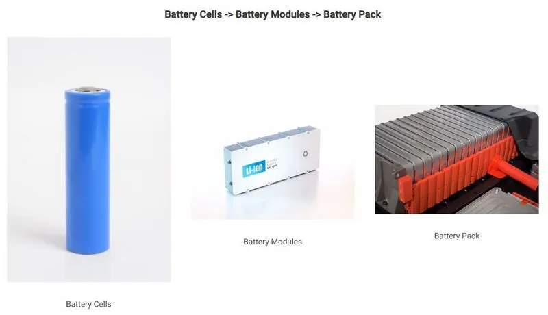
Cell holder:
Cell holders are used the place the cell in series and parallel connections and to make a battery modules.
JOINING TECHNOLOGIES IN BATTERY MANUFACTURING:
Automotive battery packs for electric vehicles (EV), hybrid electric vehicles (HEV), and plug-in hybrid electric vehicles (PHEV) typically consist of a large number of battery cells. These cells must be assembled together with robust mechanical and electrical joints. Joining of battery cells presents several challenges such as welding of highly conductive and dissimilar materials, multiple sheets joining, and varying material thickness combinations. In addition, different cell types and pack configurations have implications for battery joining methods.
joining technologies that are currently used in battery manufacturing (i.e., resistance welding, laser
welding, ultrasonic welding and mechanical joining)
Resistance Welding:
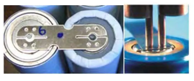
Resistance welding relies on the electrical resistance at the metal interface to cause a localized heating and fusion of materials. The pressure exerted by the electrodes, through which the electrical current flows, holds the workpieces to be welded in close contact before, during, and after the welding cycle.
Laser Welding:
Laser welding is a non-contact process that joins multiple pieces of metal through the laser. The weld is formed as the intense laser beam rapidly heats the material, typically in milliseconds [17]. Laser welding is used to weld battery
electrolyte containers, interconnectors, and bus-components. As a non contact welding process, laser welding has several advantages for battery pack manufacturing. Since welding with a low power pulsed Nd:YAG laser produces the smallest heat affected zone and a possibility of multiple sheets joining, laser welding is sometimes considered the optimum welding tool for applications involving lithium-ion batteries.

Ultrasonic Welding:
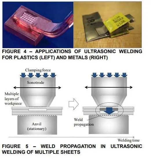
Ultrasonic metal welding is a process in which a high frequency, usually 20 kHz or above, of ultrasonic energy is used to produce oscillating shears to create solid-state bonds between two sheets clamped under pressure . Ultrasonic
welding can be used to join a wide range of types of metal sheets or thin foils. The lateral forces, generated at high frequency, break down contamination and produce an atomic bond between metal interfaces at elevated temperatures
Mechanical Joining:
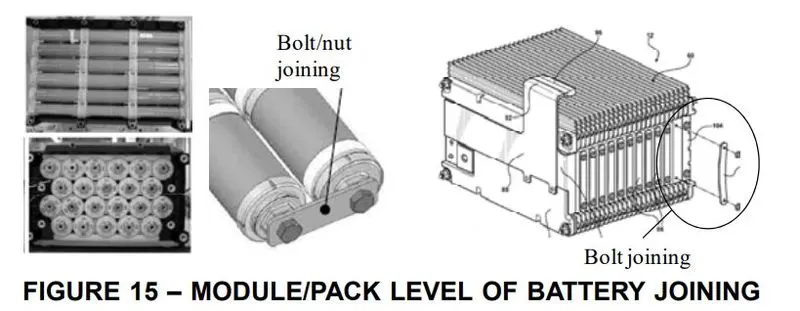
Mechanical joining can be categorized by two distinctgroups: fasteners and integral joints. Fasteners include nuts, bolts, screws, pins and rivets. Integral joints include seams, crimps, snap-fits, and shrink-fits that are designed into the
components to be connected However, when applied to module-to-module joining, welding may be not appropriate for joining those large modules due to battery maintenance and service concerns. Instead, by using
threaded bus bars or metal rods, individual units or modules can be fastened by bolts and nuts. Hence, the major advantage of mechanical joining is the ease of disassembly for maintenance and repair.
Wire bonding:
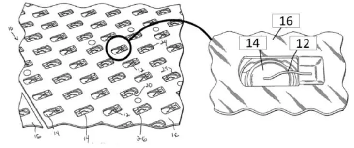
wire bonding is a frequently employed joining technology in semiconductor device technology. Here, a wire is joined onto an integrated circuit board in order to create connections. Those connections are most commonly manufactured by means of thermo-compression bonding, ultrasonic (wedge) bonding, and thermo-sonic bonding.
BATTERY PACK:
High level of battery joining such as module or pack level joining is not considered as critical as unit level joining because most of them are conducted by mechanical joining using bolts/nuts or wires.In this higher level of joining, enhancing a spatial efficiency with a large number of battery components will be a key issue while meeting all the requirements that a battery pack should have (e.g., power, energy capacity and etc.).
below image shows the battery pack architecture of various EV cars:
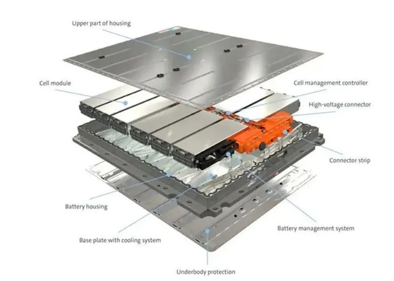
Final Battery pack with housing:
Several modules are connected in series and parallel to form a overall battery pack,modules are connected with battery management systems and high voltage and current connectors are connected and modules are placed in the battery housing made up of aluminium alloys and cooling and venting systems are attached and bottom plate with cooling system is attached and housing to cover the upper part is attached finally to form the complete battery pack.
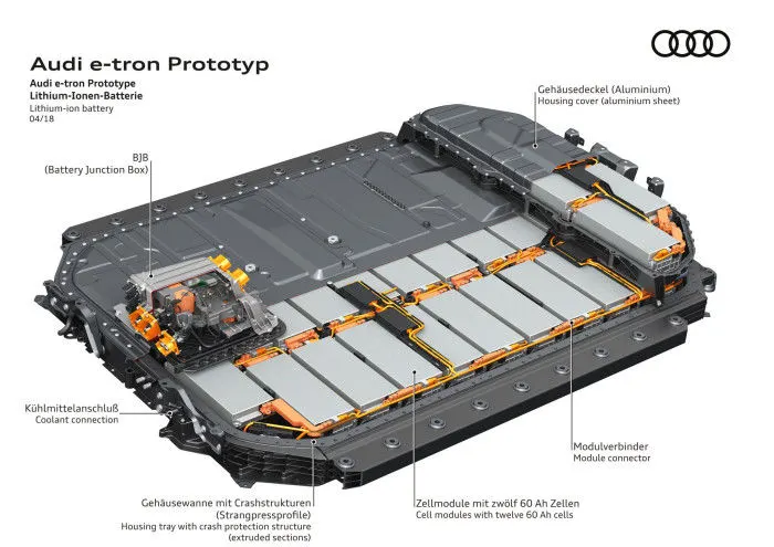
Below image shows the typical battery pack used in Audi e tron:
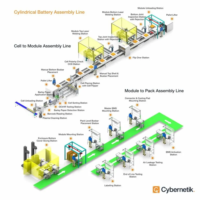
Assembly of battery pack:
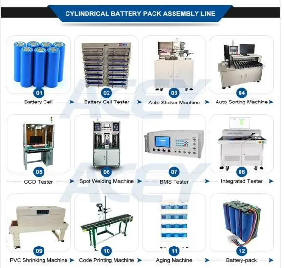
There are many process are carried out in the assembly line to get the final battery pack (from cell to final pack),which are different for various battery pack manufactures,some of the process are listed below.
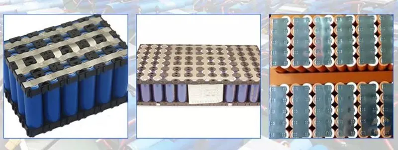
Below Images shows the cylindrical battery assembly process in factories to make battery pack:
Conclusion:
The ANR26650M1-B cell is selected and mechanical design and calculations are done to obtain a battery pack with capacity of 18Kwh by considering some assumptions. The battery pack and its enclosure construction and assembly process are studied and described. The datasheet is attached for the reference.
References:
https://x-engineer.org/ev-design-battery-calculation/
https://www.epectec.com/batteries/battery-configuration.html
Thank you
Submitted By
B.Riyaz