Project 1 Mechanical design of battery pack
PROJECT – 1
AIM:
To create a battery pack drawing of 18KWh using series and parallel connections of battery modules made up of individual Li-ion cells.
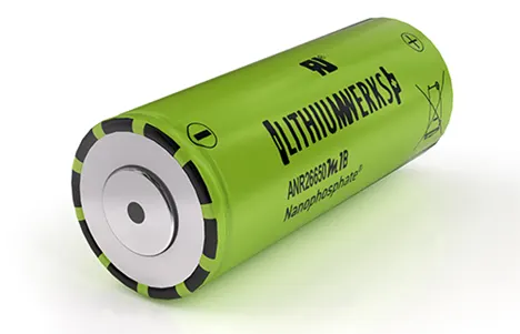
Li-ion cell for the model ANR26650M1-B from the manufacturer of Lithiumwerks.
To discuss about the enclosure used for battery pack.
Li-ion cell (ANR26650M1-B):
This Li-ion cell is manufactured by Lithiumwerks. They deliver very high power due to their use of patented Nano phosphate battery technology.
Based on the Lithium iron phosphate chemistry (LiFePO4), the cells are inherently safe over a wide range of temperature and conditions. For outstanding cycle life, stable float reliability these cells are suitable for a wide variety of power, pulse and stand by applications.
Nano phosphate battery technology offers thermal stable chemistry, fast charging, consistent output, low-capacity loss over time. It provides extremely safe conditions for while meeting most demanding customer’s requirements. Multiple layers of protections are employed on chemistry, cell and system level to achieve an energy storage solution with superior safety.
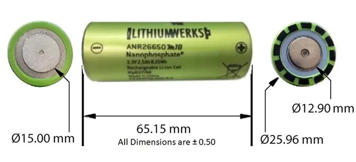
Dimensions:
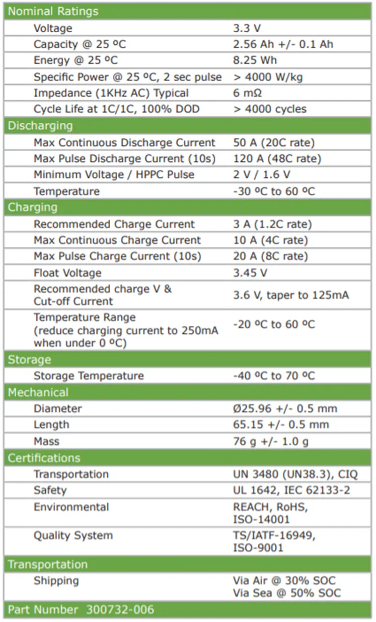
Cell specifications:
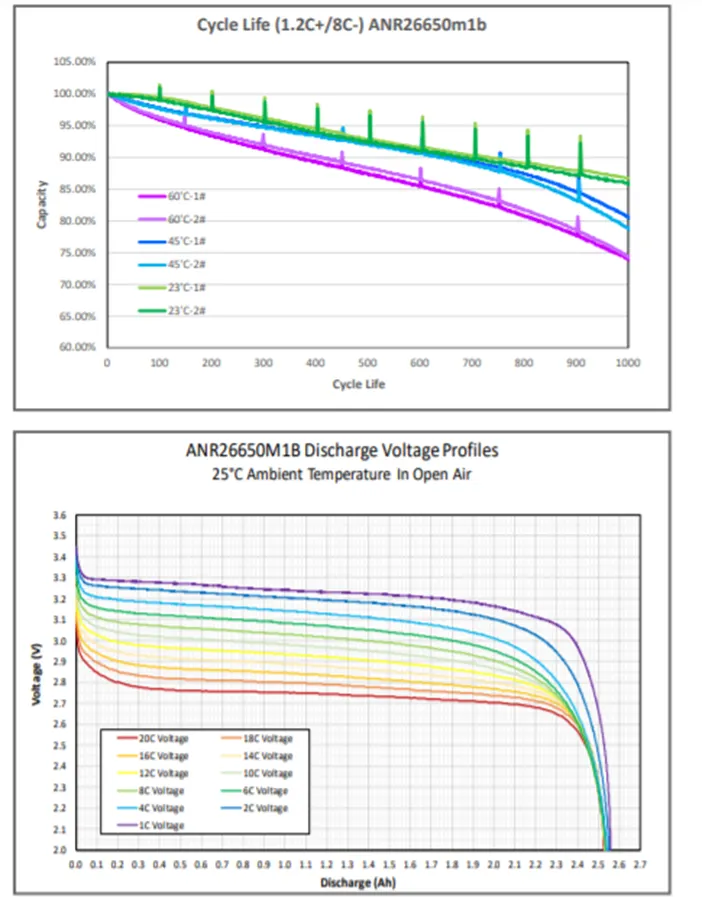
Discharge voltage profile and cycle life with respect to different operating temperature from data sheet:
Assumptions:
We are assuming the overall voltage required to operate the motor and other accessories of electric vehicle as 400V. So, we have constructed the battery pack of 18KWh for a 400 V input voltage motor.
Construction of battery pack:
To construct a battery pack initially we have to estimate the voltage requirement of the overall load of vehicle. We had assumed as 400V as mentioned above. Then the battery modules should be created in such a way that the overall voltage is matched with the load requirement voltage.
The modules can be created in series/parallel connections of individual cells. Then every module should be connected in series/parallel to construct final battery pack. In series connection-Voltage added and Current remains same. In Parallel Connection-Voltage remains same and Current gets added. Here in our case single cell voltage is 3.3V and a capacity of 2. 56Ah.Energy provided from single cell is give 8.25Wh. So, for 18KWh battery pack we need approximately (18000/8.25=2182 cells).
We have to create a single module to produce 400V for our load requirement. So, to obtain 400 V output, cells are connected in series where voltage become added and current remains same. To obtain 400V, no of cells required is approximately (400/3.3=122 cells). Thus, single module gives as 400V from 122 cells but energy of one module is not enough to run the vehicle as motor power rating is higher. The energy generated from single module is (122*8.25Wh=1006.5Wh).
So, to construct a battery pack with 18KWh with not exceeding 400V the modules are connected in parallel. In these parallel connections the currents are getting added and voltage remains same as 400V.As current increases the power of battery pack increases to run the motor load of high-power rating. Now, we have to find how many similar modules should be connected in parallel to achieve 18KWh battery pack. This can be calculated as (18KWh/1006.5Wh =17.88), which gives as nearly 18 similar modules should be connected in parallel to achieve 18KWh battery pack.
Thus, the battery model is said to be 122S18P configuration (122 series and 18 parallel connections), which gives us (122*18 =2196 cells). From this we have created overall capacity of battery pack as (2196*8.25Wh=18117Wh) which is slightly higher than 18KWh.
The overall Capacity (Ah) of battery pack is given as (2.5Ah * 18 = 45Ah).
Which means it provided 45 A of current continuously for one hour to full discharge.
Thus, 18 modules should be arranged in a way as battery pack to fit in an EV chassis.
Enclosure construction:
To find overall enclosure volume we have to find the volume of single module volume consist of 122 cells in series connection and multiplied with 18 parallel connected module volume.
Single module,
Let as assume 122 cells (single module) are divided into 2 modules of 61+61 cells.
The length of the module=No.of cell in row*(Cell dia + Margin at both side of cells) + clearance at side (2(cell dia + margin)).
=61*(26+4) +60 =1890mm.
The breadth of the module= (cell diameter+ Margin of both side of cells + clearance)
=26+4+60 =90mm.
Height of the module=Height of cell + connecting strip thickness, wires say 35 mm
=65+35 =100 mm.
Thus, the volume required for single module is 1.8*0.09*0.1 = 0.0162 m3.
Total number of modules assumed are 18*2 =36 modules, since single module is divided into two modules.
Therefore, total volume required for battery pack of 122S18P configuration construction is 0.0162*36 = 0.583 m3.
Thus, from the above results it is assumed approximately 1m3 of volume should be used for EV battery pack with additional ventilation spaces for pack.
We can assume that two modules are combined into one cabinet. So, 18 cabinets should be connected to form final battery pack.
Materials and process in battery pack construction:
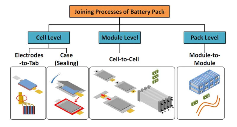
Battery pack constructions consist of three major levels of processing’s namely cell level, module level, pack level constructions. The electrodes are combined with electrolyte to various cell models as cylindrical, prismatic, pouch type cells. After case sealing cells are combined to form module level construction. Finally, these modules are combined to form pack level constructions.
Joining technologies of cells:
The interconnections between cells/modules are practised by various welding techniques. Some, of them are,
- Ultrasonic metal welding.
- Resistance welding.
- Laser beam welding.
- Wire bonding.
- Mechanical Joining.
Ultrasonic metal welding:
Ultrasonic metal welding or UMW, is a solid-state welding technique which forms a bond by applying moderate static pressure and an ultrasonic oscillation of about 20 kHz between two parts of metal. The solid-state weld is formed through the high frequency motion between the parts causing continuous shearing and plastic deformation, while also removing any oxide layers or contaminants. Most metals can be ultrasonically welded and the method is excellent for welding together thin foils, as well as thicker sheets with spot or seam welds and also wires.
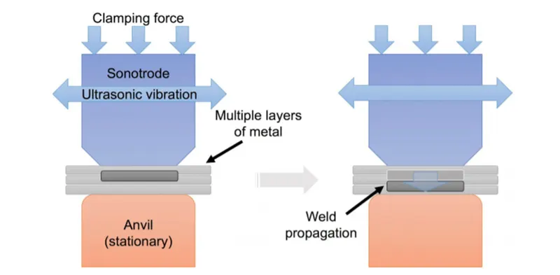
The four types of materials welded in this process can be seen as,
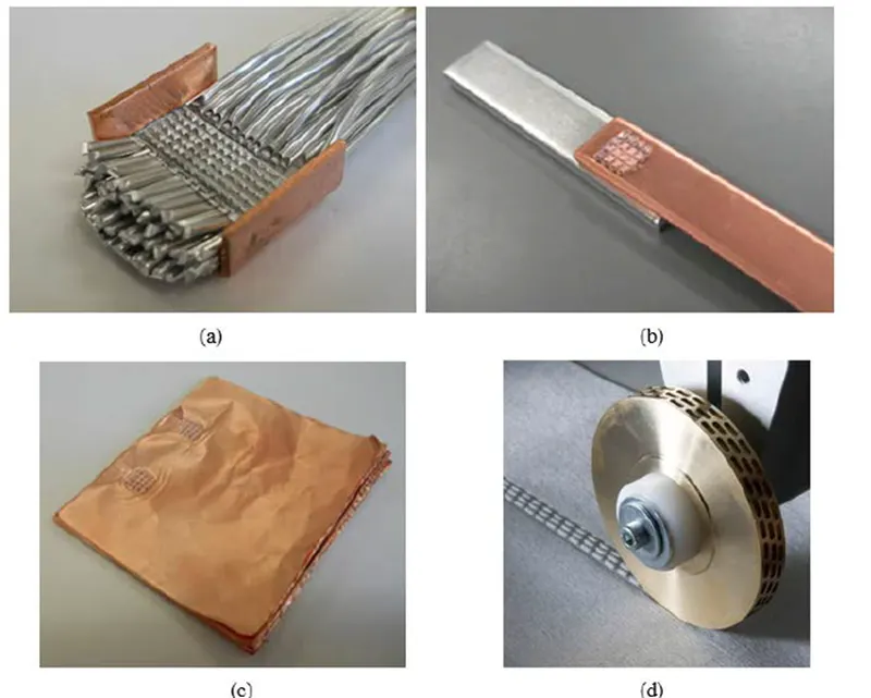
- a) Aluminium wire welding on copper.
- b) Copper and aluminium welding.
- c) Multi-layered copper foil welding.
- d) Ultrasonic seam welding.
Resistance spot welding-
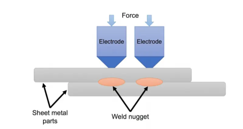
One of the oldest welding methods is resistance spot welding (RSW). RSW is a technique where two or more metal sheets are welded together through the application of an electrical current and pressure between two electrodes. The electrical resistance of the material at the interface results in the generation of heat and melts the materials together without the use of filler material or gases. The temperature increases in the affected area, the interface, and eventually reaches the material’s melting point. A weld nugget forms in the affected area after cooling. This is a small volume of the material which has melted and then fused together.
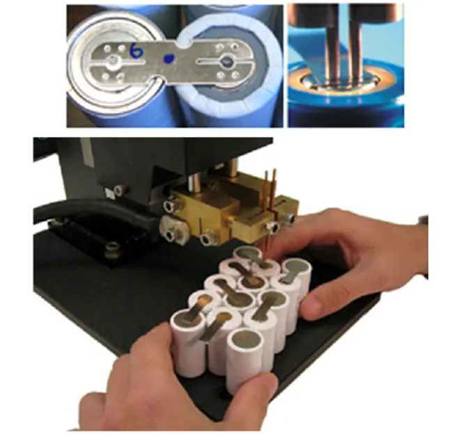
Laser beam welding-
Laser beam welding or LBW is a welding technique in which a laser beam provides a concentrated heat source that fuses the materials together.
LBW is commonly performed using keyhole mode welding in which the extreme power density of the laser beam causes the metal to melt and evaporate.
As the metal atoms evaporate from the surface, forces in the opposite direction of the evaporation causes a local vapor pressure. The vapor pressure creates a hole which is known as the keyhole by depressing the molten metal.
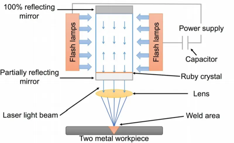
Here below shown the welding of busbars to cylindrical battery cans.
Enclosures:
Cells in series connection-
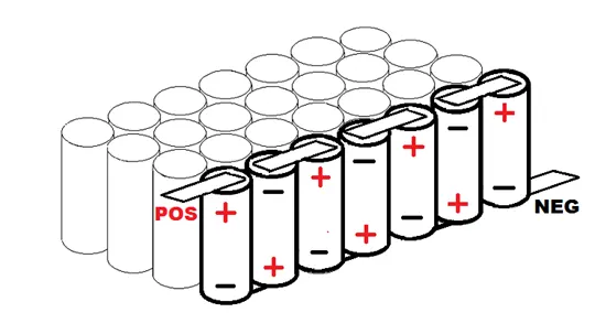
When you connect cells together in series, it doesn’t change the amps or the capacity, it only raises the voltage of the pack. Hooking them up in series means that you connect the positive end of one cell (or P-group) to the negative end of the other as shown below.
Cells in Parallel connections-
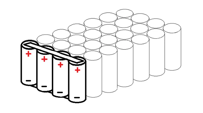
If you take several cells and connect their same-type electrodes in parallel, they all will act as though they are one large cell. Also, when you first connect them to each other, they must be at the same level of charge.
Cell holders-
These holders are used for holding the individual cells in a better posture without mis-assemble. The connections can be made accordingly to make series connections and parallel connections to form the required module dimensions.
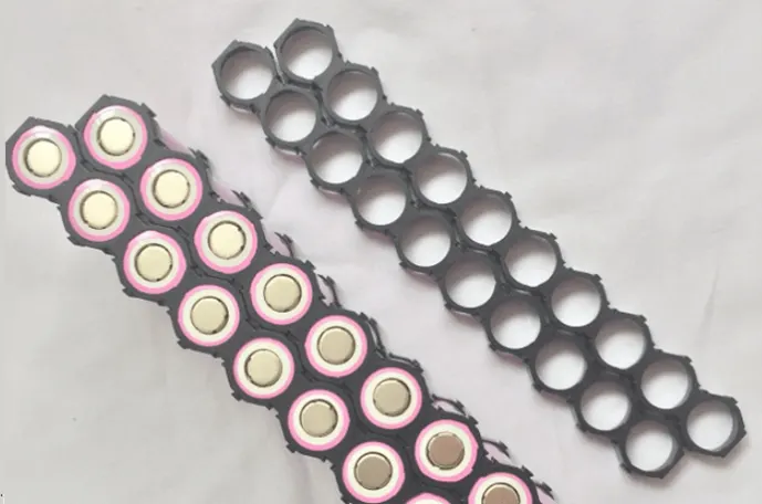
After installed the cells in an individual module the entire maximum positive terminal and maximum negative terminal are made under single pair of terminals as shown below.
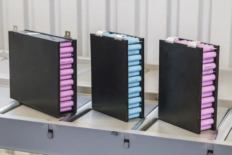
Here shown the cells are arranged and welded without using cell holders as,
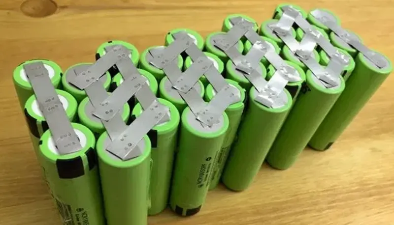
They are just covered by polymer sheet after the interconnections are made. Mostly connections with cell holders should be recommended for better safety concerns.
Battery Cabinet arrangements-
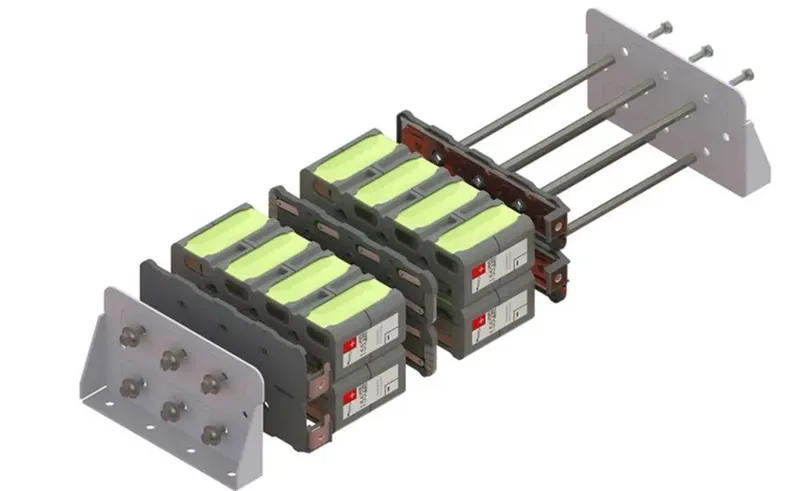
Each module is interconnected in series or parallel according to the requirement and packed as a single large cabinet pack as shown below.
Battery pack arrangement:
Finally, the overall battery pack after the arrangement of all cabinet connections with enclosure looks like this as shown below,
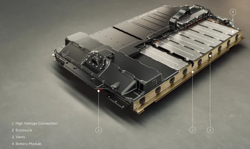
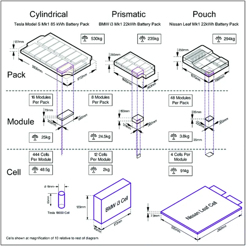
Vents holes are present with enclosure for cooling/heating the battery pack temperature according to its environment conditions. Different cell types are used by different manufacturers of EV such as Cylindrical, Prismatic, Pouch types. The pack constructions are different for every manufacturer. Below shown the battery pack constructions process of Tesla, BMW and Nissan Leaf.
Conclusion:
Lithium Ion and Lithium-Ion Polymer batteries are a great power source for some applications but they require preventive protection during discharging and charging.