Project 1 Mechanical design of battery pack
EV Live Batch-21
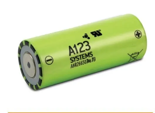
Cell: ANR26650M1-B Details:
| Parameters | dimension |
| Cell Dimensions | ᶲ26 x 66 mm |
| Cell Weight | 76g |
| Cell Capacity(nominal/minimum)[0.5C Rate] | 2.5/2.4 Ah |
| Voltage(nominal) | 3.3V |
| Internal Impedance (1kHz AC typical) | 6mΩ |
| Power | 2600W/kg |
| Recommended standard charge method | 2.5A to 3.6V CCCV, 60 min |
| Recommended Fast Charge Method to 80% SOC | 10A to 3.6V CC, 12min |
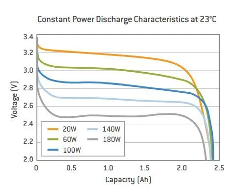
| Maximum continuous discharge | 50A |
| Maximum pulse discharge(10 sec) | 120A |
| Cycle life at 20A dischsrge, 100% DOD | >1,000 cycles |
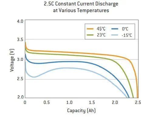
| Operating Temperature | -30°C to 55°C |
| Storage Temperature | -40°C to 55°C |
Theory:
Understand when sizing a battery is what type of application it is? A battery is basically an electrochemical energy storage device. And we can divide battery usage into two categories: either power or energy. A power battery can be described as focused on providing “instant” power for vehicle acceleration.
The power battery is not intended to provide long-term energy to operate a system. Think of a power battery as one that discharges its power and energy in very small time frames, usually from seconds to tens of minutes. The energy battery is intended to provide a long and relatively slow discharge. Think of it as one designed to discharge its energy over 1 h or longer.
We are using a high-performance Nanophosphate lithium iron phosphate (LiFePO4) battery technology that delivers high power and energy density combined with excellent safety performance and extensive life cycling in a lighter weight, more compact package. These cells have a low capacity loss and impedance growth over time and high usable energy over a wide state of charge (SOC) range, allowing our systems to meet end-of-life power and energy requirements with minimal pack oversizing.
Calculation as per assumptions:- 18kWh Battery Pack
calculation for designing an 18kWh battery pack, basically 18kWh is the energy required to achieve the vehicle its proper range. It is depending upon the voltage (V) parameter and ampere-hour or capacity (Ah).
Here we design a high voltage battery pack for an electric vehicle to achieve its range of up to 300 km. For this calculation, I assumed 200 V is a nominal voltage for a series connection.
Basically, the value of the volume of the cell is used to find out the total volume of the battery pack.
Single Cell Energy (Wh) = Cell Capacity (Ah) x Cell Voltage (V)
= 2.6 x 3.3
= 8.58 Wh
Single Cell Energy Density
Volumetric energy (Wh/m^3) = Single Cell Energy / Volume of each cell
= 8.58 Wh / 0.03451 m^3
= 248.62 Wh/m^3
Gravimetric energy (Wh/kg) = Single Cell Energy / Single Cell Mass
= 8.58 Wh / 0.076 kg
= 112.89 Wh/kg
Calculation of High Voltage Battery Pack
For the design and calculation of the battery pack here, I assume a vehicle to achieve 300 km in an 18 kWh battery pack. Also, I assume 200V nominal voltage for the series connection.
So,
Vehicle Range = 320 KM (assumed)
Battery Pack capacity = 18.121 kWh or 18121 Wh (For better and accurate calculation here I change kWh to Wh)
Now,
We will calculate per km average energy = 18121 / 320
= 56.628 Wh/km
Let's assume the nominal voltage for a series connection is 200V.
basically, it's dependent on the motor power. We can decide the value according to the motor.
no. of series cell = Pack voltage / cell voltage
= 200/3.3
= 61 cell(approx.)
Approximately 61 cells have been required to provide 200V.
Energy for battery pack = no. of series cell x single-cell energy
= 61 x 8.58
= 523.38 Wh
so, no. of cells required connected in parallel is,
= Battery pack total energy(Wh)/ Energy for battery-pack (Wh)
= 18121 / 523.38
= 35 cells(approx.)
35 cells approximately will be required in parallel to provide a proper capacity.
Now battery pack capacity = no. of cells connected in parallel x single cell capacity
= 35 x 2.4
= 84 Ah
The value of battery pack capacity used for delivering the required power by vehicle is,
Total no. of cells required = no. of series cells x no. of parallel cells
= 35 x 61
= 2135 cells
2135 cells will be used to make a complete battery pack.
Mass of the battery pack = total no. of cells in battery pack x mass of single cell
= 2135 x 0.076
= 162.26 kg
This is the total weight of the battery pack.
The total volume of battery pack = Total no. of battery pack x volume of single cell
= 2135 x 0.0345
= 73.6575 m^3
This is the volume for the battery pack.
cell peak current (A) = C rate (max pulse charge current) x single cell capacity
so, C-rate (discharge) = cell peak current (A) / single cell capacity
= 50 / 2.6
= 19.23
This is the maximum continuous discharge rate for our cell.
so, Battery pack peak current(A) = cell pack current x no. of cells connected in parallel
= 50 x 35
= 1750 A
It is used for the operation of the battery pack.
In this way, a vehicle will decide how much power is required to move.
Battery pack peak power(w) = Battery pack peak current x voltage of the series connection
= 1750 x 200
= 350 KW
Cell continuous charge current (A) = C-rate (Max continuous charge current) x single cell capacity
= 10 x 2.6
= 26 A
Battery pack continuous charge current (A) = Cell Continuous current x no. of cells connected in parallel
= 26 x 35
= 910 A
This is the current required when we charge the whole pack of battery pack,
Battery pack power(KW) = battery pack continuous charge current x voltage
= 910 x 200
= 182 KW
Designing of battery pack enclosure:
- Dimension of battery:
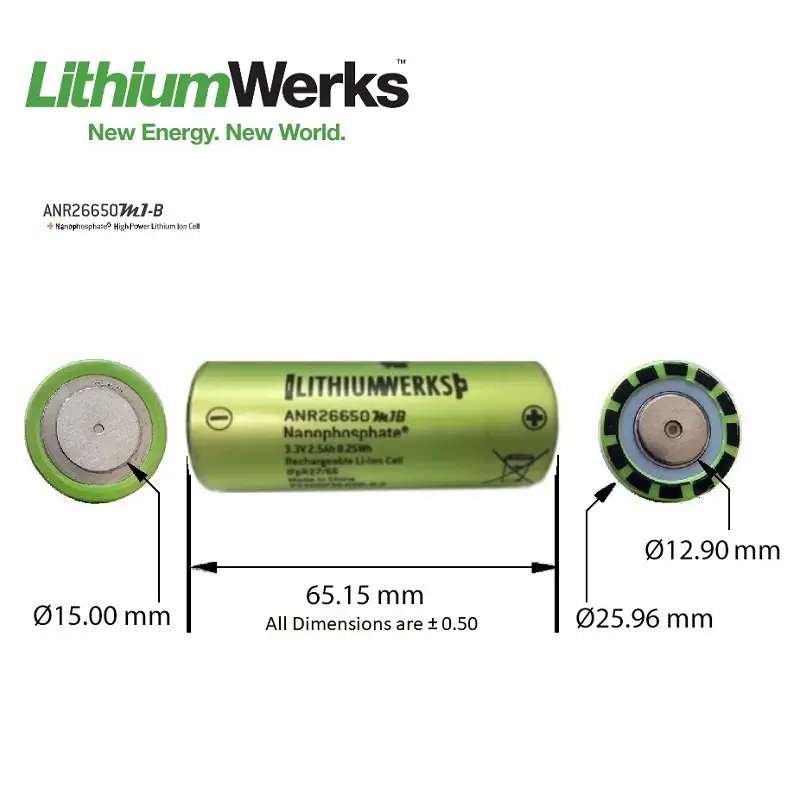
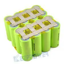
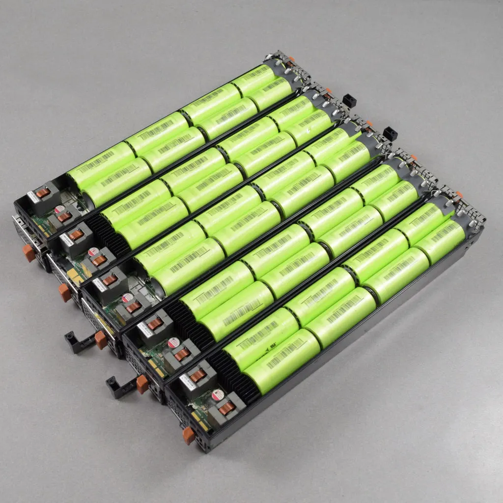
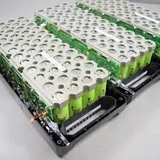
from the above picture, we can see the dimension of the battery shown in Figure 1.
other components used in battery pack designing are casing, connection links, temperature sensor, microcontroller etc.
Comparison of Structural Characteristics of Small Cylindrical Cell:
Criteria Small Cylindrical
Casing - Metal
Connection - Welded nickel or copper strips or plates
Retention against expansion - Inherent from the cylindrical shape
Appropriateness for production run - Good, welded connections are reliable
Field replacement - Not possible
Delamination - Not possible
Compression force holding - Excellent
Lead stress - No
Safety - Good, integrated with PTC
Heat sink wrapping - yes
Nickel Strips:
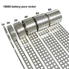
Nickel strip is generally used in battery building. It's due to its efficiency of usage in spot welding and soldering as well as its high corrosion resistance over time. It has good properties and excellent resistance to many corrosive environments. Pure nickel will never get rust after it is applied to battery packs. It won’t affect the current transfer between batteries.
Pure nickel strips are the material you want, but many vendors swap out it for nickel-plated steel strips, which are poorer and have greater resistance – not suitable for most battery projects.
100% pure nickel strip. verify all of our strips to assure that you are getting a high-quality pure nickel. It also solders incredibly quickly, so you can weld them onto your existing busbar connections to raise the supply of current you can pull through the busbars.
Battery Enclosure:
The growth of electrification brings many new challenges, one of which is to design and manufacture a robust battery box or housing. An efficient battery housing has many attributes that aid passenger and battery safety and assist in thermal management while protecting the battery from the harsh environment under the vehicle and in an accident. The system must be produced within the financial and weight constraints of the vehicle.
The battery box consists of four primary structural pieces: top cover, bottom cover, internal structure, and side-impact crash protection structure. In the image below, the primary load-bearing structural components are identified as the crash structure and the battery frame: