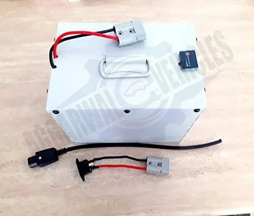
Project 1 Mechanical design of battery pack
- Batterypack comprises of thousand number of cells, Cells are connected in either parallel pr series pattern, an specific number of cells are combined and it is called as module , then these modules are arranged together to make a batterpack.
- Along with cells, there are heating/cooling arrangement is also given, Battery management system(BMS) which is used for monitoring and sensing cell level voltages, currents and temperatures.
- Powerline and communication cables are connected in between BMS and cells for monitoring battery performance as well as for safety concern.
- Various materials are used at different level of batterypack formation.
- Let us start from Cell structure.
CELL STRUCTURE:
- A single cell can have four different form factors 1. Cylidrical , 2.Prismatic, 3.Pouch 4. Button cell
- Each of four types are made up of many layers as shown in image below.
- There are 7-8 layers of material form a jelly roll wrapped around a centre pin.
- Layers are suh that starting from cathode(+ve electrode), alumunium (+ve current collector), again cathode, than a separator, Graphite(-ve anode), copper(-ve current collector) again graphite and then a separator. These layers repeat in similar ways in each type of cell over and over.
- There are protecting vents to equalize pressure inside as outisde the cell as the atmoshperic disturbances like temperature change, pressure change occurs.
- Inside cell or we can say inside jelly roll, electrolyte is filled and it is sealed by a Plastic enclosure called gasket.
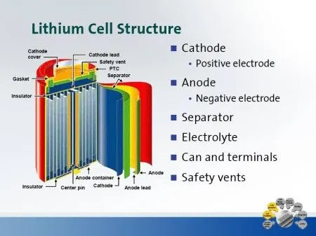
- The top cap is nothing but a positive terminal and the remaininig cell case is a negative terminal both termianls are separatd by an insulating ring.
- Now, let's see the making of batterypack starting from cell level.
CELL To MODULE CREATION:
- We have given a lithium ion cell
Cell model: ANR26650M1-B.
Battery pack capacity: 18 kWh.
- To calculate the number of cells in series and in parallel connection, we need to see this cell specifications.We are going for some calculations as per the cell datasheet which is shown below.
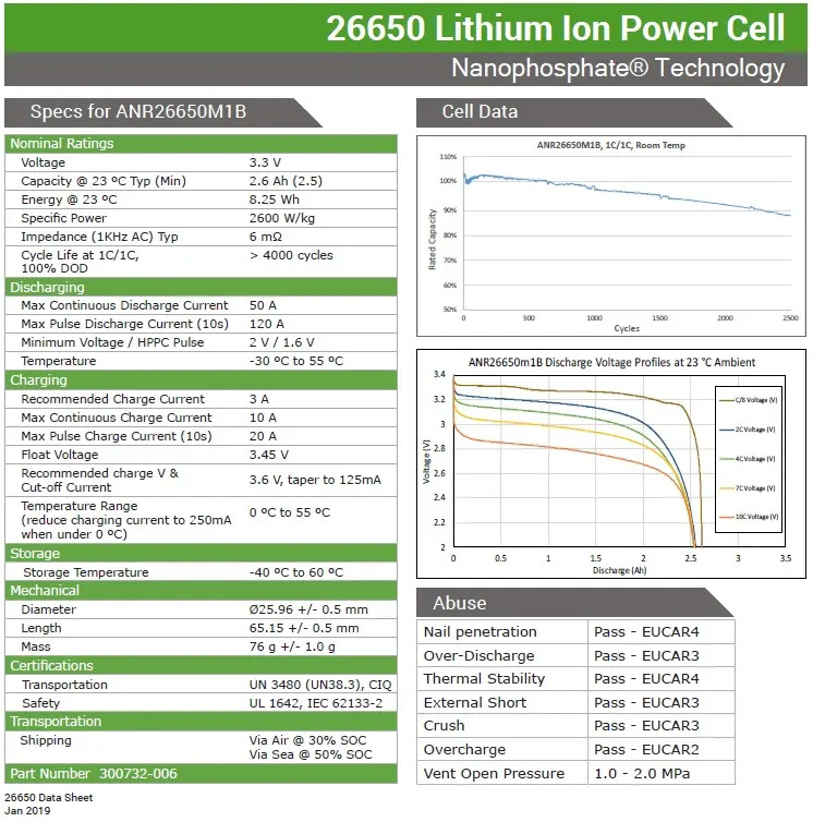
- Number of cells are calculated from the rated current capacity , voltage value of a single cell that is 2.6A and 3.3V.
- We need to assume required voltage for calculation, let say our requirement is 330V and 18 kWh(given).
- Number of cell to be connected in series will be: Required voltage / Cell voltage i.e., 330/3.3=100 Series cells.
- Now calculating number of parallel branches as per required Ah capacity.
- Required battery capacity(in Ah)= 18000 kWh / 330V = 55 Ah (approx).
- Number of parallel connected branches = Required Battery Capacity(in Ah)/ Cell capacity(in Ah) = 55 Ah/ 2.6 Ah = 21 parallel branches approx.
- It is suggested to connect cells in parallel to make a module so that there is less chances of voltage mismatch among cells.
- A module is of 21 cell in parallel to fulfil Ah capacity of 55 Ah and there are 100 such modules connected in series to fulfil required voltage of 330V.
- Thus, our final batterpack array configuration is made of 21P100S , a grand total of 2100 cells.
- Now, we see how cells are interconncted, which materials are used and what process required to do connections such that they can bear mechanical stress to some extent.
CELL ELECTRICAL CONNECTIONS;
- Generally, connections are made through wires but in case of battery scenario is slight different.
- Let's see how it looks like when cell connections are made with solid strended copper wires.
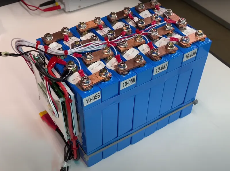
- This is only 14 cell connected through solid copper wiring, but just think about it when cell are above thousand in number, it will definitely create a mess.
- That is how we are not supposed to make cell interconnections as there are many aspects need to take into account, this kind of wiring take alot of space , also costier and not safe. Heat generation is the major problem here.
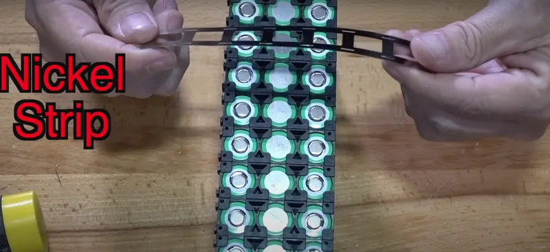
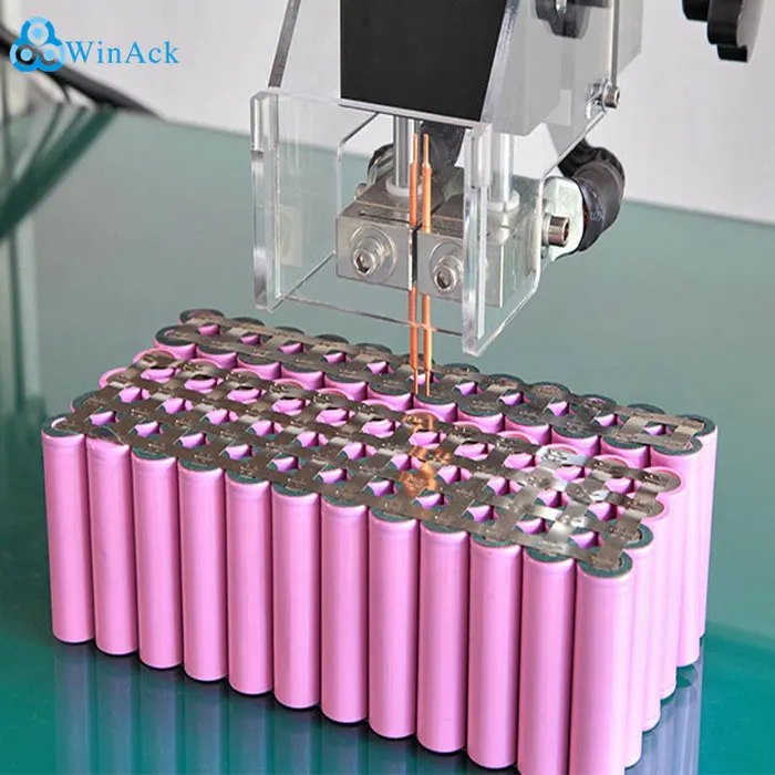
- For wise connections, copper aluminium fillet or overlap weld is used and by using spot or laser welding or wire bonding this strips are welded on the cap of cells.
- SIGMACLAD is material which is used for connection, it consists of Copper, nickel,steel.
- SPOT WELDING:
- WIRE BONDING:
- After making proper connections, battery main terminals (+ve and -ve)are taken out and various protection devices and sensors are provided as shown in figure below.
- Let's discuss about some sensing and protection devices connected to battery:
SENSORS AND PROTECTION DEVICE:
- Sensors like temperature sensor ,voltage sensors are continuously measuring these parameters for each cell.
- Current sensor is meansuring pack current, and voltage sensors are measuring pack and Cell voltages.
- All measured values are then send to BMS , and there are limits set for overcurrents and overvoltages and also temperature limits, if any of the measured value exceeds the limit the BMS enables protection devices like Fuse to take action and disconnect the battery terminal from load.
- There are communication cables (CAN) in between sensors and BMS.
- Also BMS is responsible for cell balancing , if their is mismatch found and cell SOC the balancing command is triggered by BMS to the balancing circuit.
THERMAL MANAGEMENT:
1).THERMAL MANAGEMENT:
- As we know that a battery pack is made up of large number of cell modules and modules are either series or parallel combination of cells.
- There is rise in temperature in batterypack whenever in use that is because of current flow, we can not ignore this heating effect as it may create hotspots inside batterypack and may lead to explosion if not managed properly.
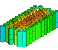
- In image shown above, cells presents at the middle of batterypack are getting heated more than the surrounding cells because there is no means of heat dissipation, hence there temperature is rising faster than surrounding cell.
- If this heat is not dissipated by any means, it increases battery weight, reduces battery life and capacity, if battery is being in EV the top speed and range also going to affect.
- It may cause thermal runaway because cells in middle passing heat to their neighbour cells and if one cell get heat up and lead to thermal runaway it is going to affect all its neighbour cells too and overall battery pack may explode.
- There are mainly two ways for thermal management, one is Passive management and another is Active management.
PASSIVE THERMAL MANAGEMENT:
- Passive thermal management uses heat sinks generally made up of aluminium.
- They are placed among modules such that the heat from the innermost cells can be tranferred to outside environment.
- Image below shows how heat sinks are made to install among cells.
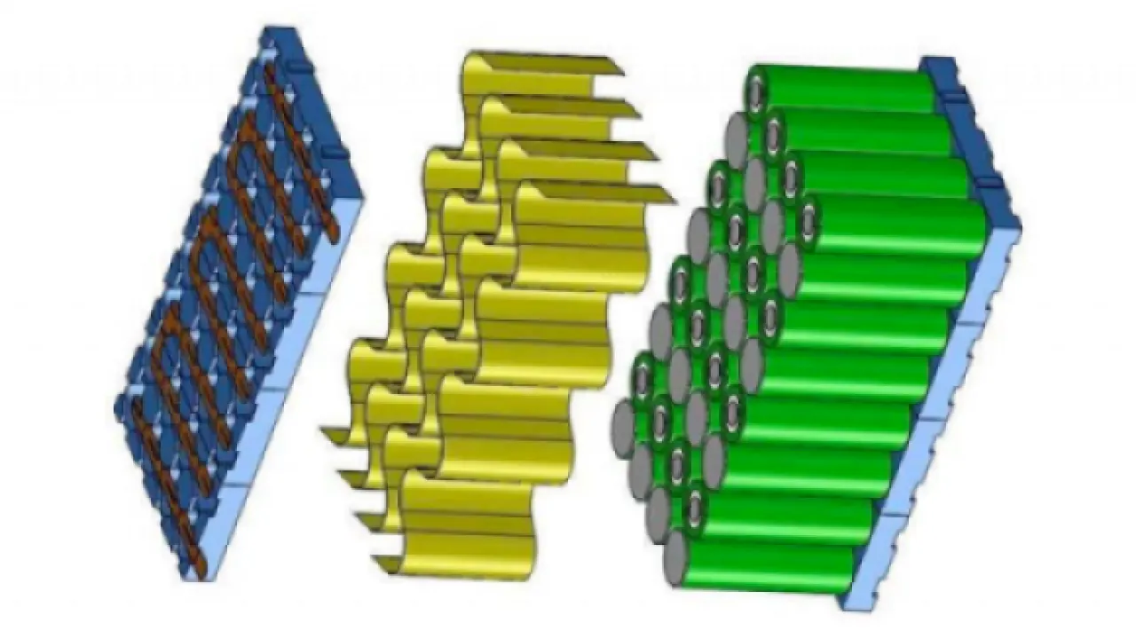
- This technique doesn't require extra setup except these heat sink foils, so this is the natural and simplest way of thermal management.
ACTIVE THERMAL MANAGEMENT:
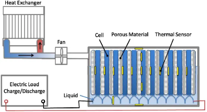
- There are four ways to do active thermal management which are shown in image below.
- This technique requires to setup extra components for battery cooling.
- Along with heat sink there are air blowers to cool down the cells.
- Instead of making foils there are fins(made up of aluminium) in which water or oil is continuously flowing inside, once the liquid gets heat up it goes to radiator where fans are cooling down this liquid.
- How Active balancing can be done is shown in image below.
- Phase changing material (PCM) are used in some kind of systems.
- There is setup of evaporator and condensor such that the heat coming out from batterypack evoporates the liquid present in pipes and this gas is then get condense by condenser, condensed liquid then send to the fins and this process continues.
- Thermal management using PCM is shown below.
- There is one more kind of active thermal management called immersion type in which the whole batterypack is filled with coolant and sealed.
- Liquid flow is happening so that once liquid heated up it is then replaced by cool liquid.
- This is the indirect method of cooling
ASSEMBLING BATTERYPACK:
- Till now, we have discussed about how cells are arranged to make module, Cell electrical connection, Sensors and thermal management of batterypack.
- Now we are going to assemble all and make a whole pack by taking given cell model:ANR26650M1B.
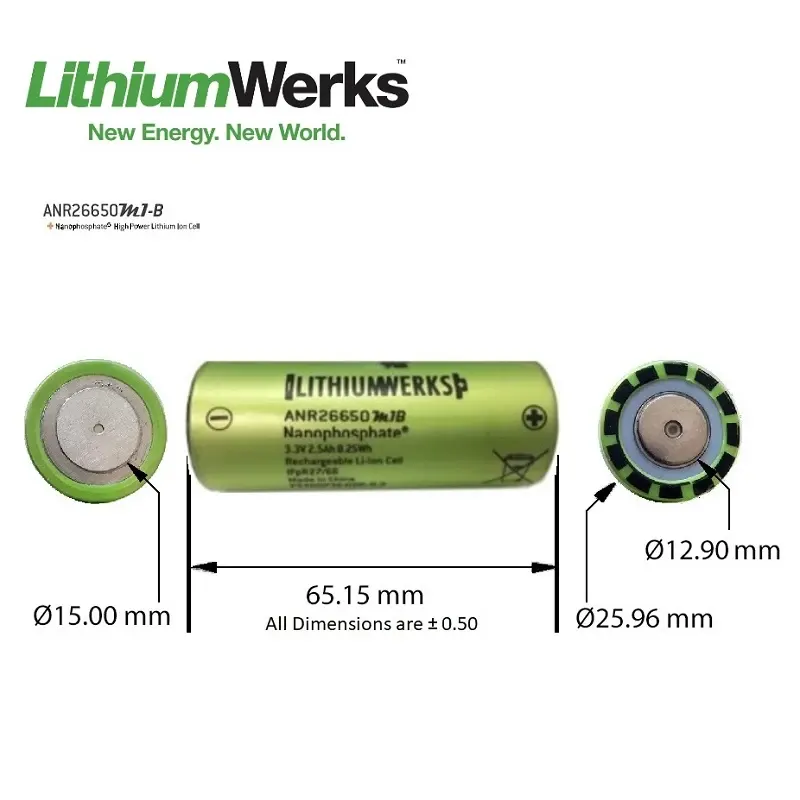
- Dimensions of Cell with tolerance value is shown in above image.
- Our cell has a diameter of 25.96mm approximately 26mm with tolerance of ±0.50 mm and height of cell is 65.15mm with tolerance of ±0.50 mm.
- The Top ring cap innermost ring has diameter of 12.90±0.50 mm and the inner ring diameter of bottom cap is 15±0.50 mm.
- While assembling cells into module , make sure that there is enough gap left between cells.
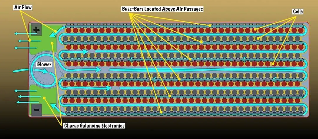
- Let's assume gap left between cells is used to put Thermal management system like coolant manifolds or heat sink is 5 mm ,we have taken air blower cooling because LiFePO4 do not need much cooling ,also additional gap must be left for the tolerance value i.e., 0.50 mm here.
Calculating the Length ,Width Height:
- If all 100 modules are arranged in such manner that 50 modules in one row and other 50 modules in next row we can avoid larger length of batterypack.
- Length calculation(with cell only): 51*(26+0.50+5)mm = 1606.5 mm = 160.65 cm,so there will be two row of 13.51 cm.
- Batterypack width is decided by 21 cells in each modules which are connected in parallel.
- Width calculation: 21*(26+0.50+5)mm = 661.5 mm = 66.15 cm.
- Total length and width can be calculated when BMS is also installed along with modules.
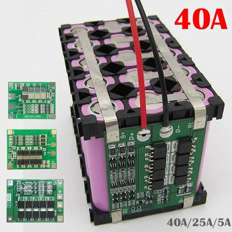
- BMS can be put onto the cell as shown above, so it do not take large space, let's assume 10 mm length required for BMS.
- Total length: 1606.5 mm + 10 mm = 1616.5 mm =161.65 cm.
- Height of battery pack: Along with cell height that is 65±0.5 mm there are sensors and protection devices are mounted on Cell.
- Sensors are embedded on a Foil based component called as Flexible PCB,Let's assume height of 5 mm required for sensors so total height will be 65.5+5= 70.5 mm = 7.05 cm.

- A lot of wiring can be replaced with this single foil based PCB .
- After doing assembly of all components, this stuff is to be fit and seal inside a casing called battery housing.
- If battery is be used in EV then Battery housing is made according to the available free space in car ,the shape and size of housing should be according to that space.
- Thus, Our battery is now ready to use.