Project 1 Mechanical design of battery pack
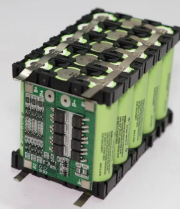
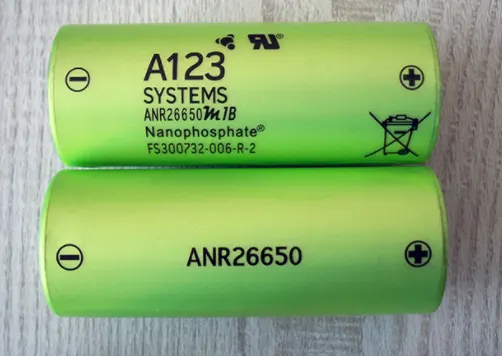
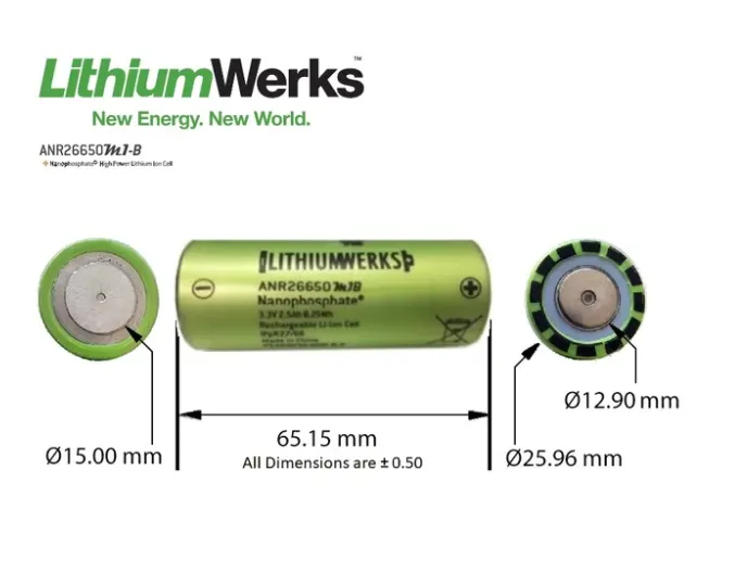
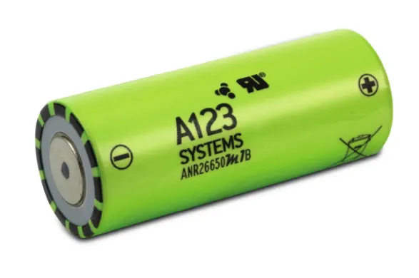
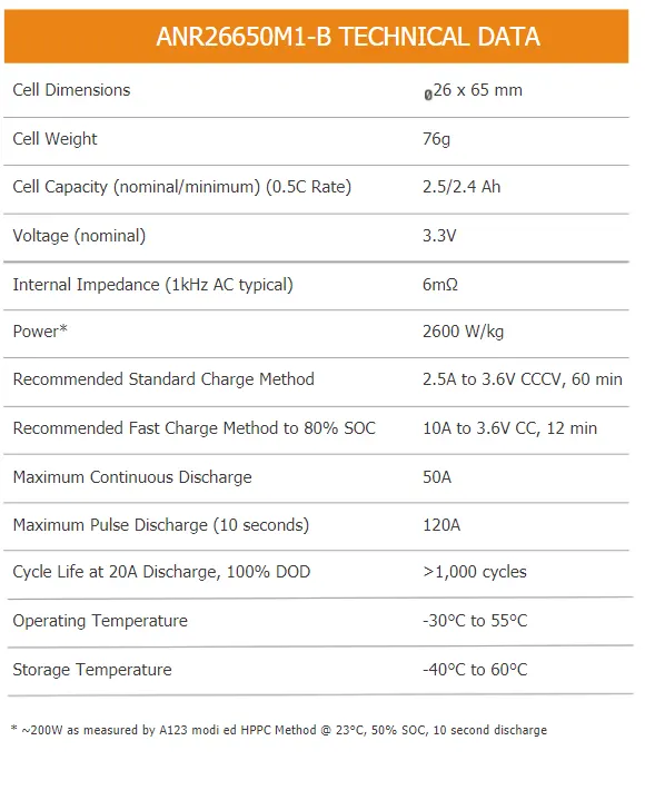
STUDY - The Project is about the mechanical design of the Lithium-ion battery pack. In this project the battery selected for the design is ANR26650M1-B and the necessary assumptions were made from building the cell to a module and then the battery pack.
INTRODUCTION -
An electric battery is defined as a device that makes use of either one or an assembly of electrochemical cells that convert the stored chemical energy within them into electrical energy. Each cell has a positive terminal, cathode, and a negative terminal, anode. The individual cells are connected in various combinations of series and parallel connection to get a battery of desirable characteristics.A battery pack is a set of any number of (preferably) identical batteries or individual battery cells. They may be configured in a series, parallel or a mixture of both to deliver the desired voltage, capacity, or power density. The term battery pack is often used in reference to radio controlled hobby toys and battery electric vehicles. Components of battery packs include the individual batteries or cells, and the interconnects which provide electrical conductivity between them. Rechargeable battery packs often contain a temperature sensor, which the battery charger uses to detect the end of charging. Interconnects are also found in batteries as they are the part which connects each cell, though batteries are most often only arranged in series strings.
An advantage of a battery pack is the ease with which it can be swapped into or out of a device. This allows multiple packs to deliver extended runtimes, freeing up the device for continued use while charging the removed pack separately. Another advantage is the flexibility of their design and implementation, allowing the use of cheaper high-production cells or batteries to be combined into a pack for nearly any application. At the end of product life, batteries can be removed and recycled separately, reducing the total volume of hazardous waste.
TERMS RELATED TO BATTERY-
State of Power(SOP):- The amount of power available for a defined time interval given the current power usage, temperature and other conditions.
Current:- Current in or out of the battery.
Voltage:- Total voltage, voltages of individual cells, minimum and maximum cell voltage, or voltage of periodic taps. In order to maximize the battery's capacity and to prevent localized under charging or over charging, the BMS may actively ensure that all the cells that compse the battery are kept at the same voltage or the State of charge, through balancing.
Temperature:- Average temperature, coolant intake temperature, coolant output temperature or temperature of individual cells.
State of Charge(SOC):- Deopth of charge(DOD) to indicate the charge level of the battery.
State of Health(SOH):- A variously defind measurement of the remaining capacity of the battery as % of the original capacity.
ANR26650M1-B :- A123’s high-performance Nanophosphate lithium iron phosphate (LiFePO4) battery technology delivers high power and energy density combined with excellent safety performance and extensive life cycling in a lighter weight, more compact package. This cells have low capacity loss and impedance growth over time as well as high usable energy over a wide state of charge (SOC) range, allowing the systems to meet end-of-life power and energy requirements with minimal pack oversizing.
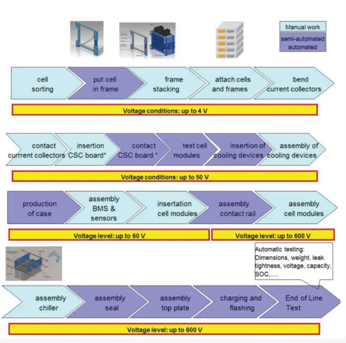
⦁ The 1st step is to determine the configuration of cells, i.e. how many total cells are required, how many in series and how many are in parallel are need to connected. This is the 1st step in the design process.
⦁ The 2nd step is to design a mechanical structure around the cells in order to protectand also support them. This step requires knowledge of electrical, mechanical and thermodynamic requirements and properties of the cells, application, and the materials used in the pack.
⦁ The 3rd step is to design the protection method of the cells, particularly electrical protection. The pack must be protected from short circuits both internal and external to the pack as well as excessive charging and discharging imposed on its terminals.
⦁ The 4th step is to design a control system that monitors and manages the cells, keeping them from being damaged and maintaining the pack at peak performance.
⦁ Finally, a pack performs best when it is used properly. The final section of this chapter describes how to charge and discharge the battery pack to make it perform its best.