Project 1 Mechanical design of battery pack
Objective:
- To design a battery pack of 18kWh capacity using ANR26650M1-B cells.
Cell specifications:
- The ANR26650M1-B cells are manufactured by A123 systems.
- These cells uses a LFP chemistry Lithium Iron Phosphate[`LiFePO_4`]
-
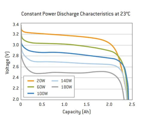
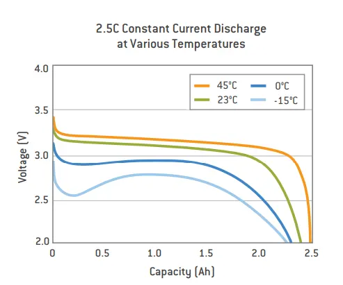
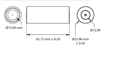
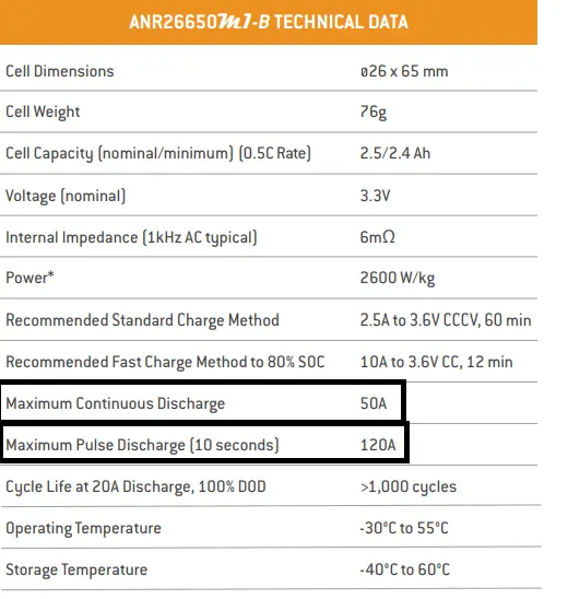
Parameters Values Units Nominal voltage 3.3 V Maximum Capacity 2.5 Ah Max continious Discharge 50A A Cell weight 76 g Cell dimension 26*65 mm
Cell Energy Density:
| Parameters | Value | Units |
| Cell Nominal Capacity | 8.25 | Wh |
| Gravimetric Energy Density | 108.55 | Wh/kg |
| Volumetric Energy Density | 242.86 | Wh/l |
Formula used:
- Cell Capcity = Cell voltage * cell Ah unit:Wh or kWh
- Gravimetric energy Density = single cell capacity/cell weight in kg unit:Wh/kg
- Volmetric Energy density = Single Cell capacity / Cell colume in L unit: Wh/l
Battery Pack Specification:
- To design a battery pack we must first decide what should be the pack energy, here in this case pack energy is 18kWh.
- In general the usable capacity is different from total capacity.The former will always lesser than latter.In order to overcome this we must add some percent of its total capacity which is usually 2 to 10%.For example this is applicable in Electricity Generation,there they used 10% loss.
- So considering this I am going to design a battery pack of 19.8kWh(10%).
- Next we want to decide the Nominal Voltage of the pack and this decides the no.of cells connected in series.here I 220V system
- The no.of cells connected in parallel decides the total Ah of the battery pack.
No.of Cells calculation:
No.of cells connected in series = Pack voltage / Nominal voltage of single cell
= 220/3.3
= 66.67(67 cells are connected in series)
No.of cells connected in prallel = Total pack capacity/(Pack voltage * single cell Ah capacity)
= 19800/(220/2.5)
= 36 no.of cells are connected in parallel
- From above we came to conclude that we need to connect 68 (to make symmetry for calculation) cells in series and 36 cells in parallel. so totally we required 2,448 cells.
Pack construction:
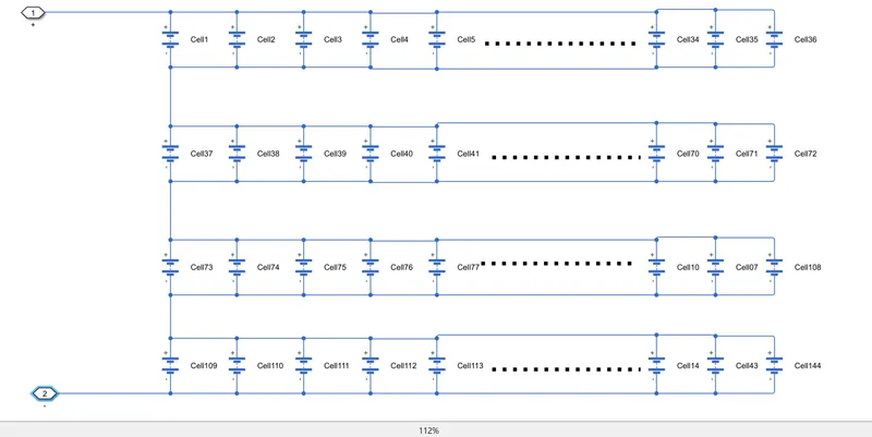
- The entire pack is divided into 17 modules and each moduels contain a 4 set of 36 cells connected in parallel and each sets are connected in series.So each modules contain 144 cells and their controllers.
- The module Nominal voltage is 13.2V and its Ah capacity is 90Ah.
Module Level:
Pack:
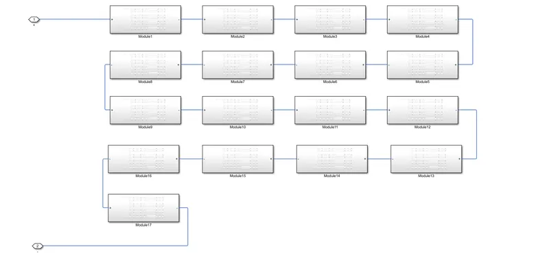
- Module dimensions are 936*104*90 in L*W*H all in mm(cosidering 0mm gap between each cells for providing cooling).
Battery Pack Assembly:
The materials that required for assembling the battery pack,
- Battery Holders or a battery mount is an integrated or separate cavity to hold cells.t is used to hold the cells securely and power the device it is attached to.
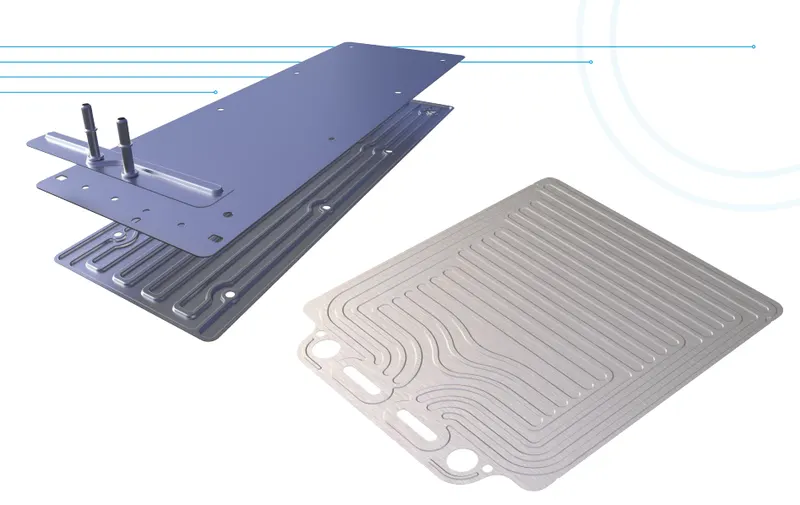
- Cooling Plates are Built with lightweight aluminum, the battery cold plate stabilizes battery cell temperature and provides optimal temperature uniformity. Featuring counterflow and double-side cell loading designs, it extracts heat from the lithium-ion battery cells and enables fast charging.In TESLA they opt for side cooling of cells which will increase the area of modules and In LUCID Motors they go with bottom cooling techinques which avoid the cooling pipe which circles around the cell.In some cases a coolinf fans is also used outside the module level and heating plates are also used inorder to provide proper heating in low/cool temperature because at very low temperature the battery doesn't work properly,it will loss its capacity.
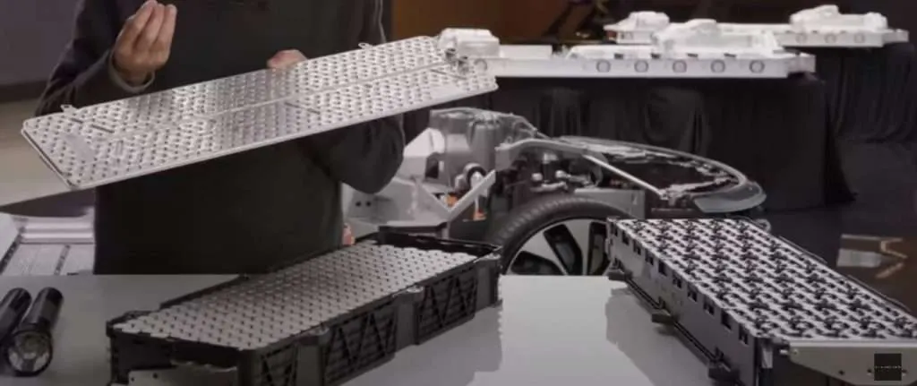
- Contactors and Fuses: The contactors helps to make and break the circuits and the used to isolate the module/entire pack incase of fault.The Fuse is used as primary protction of battery pack/cells from high current.There are many different rating of fuses are available and they are connected to cell level as well as module level.The fuse are selected according to module level and enite pack level maximum current because they are different.
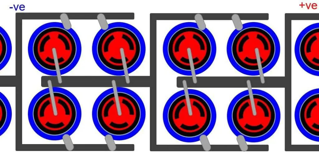
- Bus bars are a conductor which runs entire battery pack which will collect the current from every individual cells.These cells are madeup of either aluminum or copper bars.They are mostly laminated.They are joint to cells as shown in above.
- Sensors are used to measure the voltage,current and temperature to determine the capacity and performance of individual cells.They are incorperated in PCB with the battery management systems.These datas from the sensors will help to determine the SoC,SoH and range charging time required etc .
| Pack Level | Module Level | Cell Level | |
| Nominal voltage | 224.4V | 13.2V | 3.3V |
| Ah Capacity | 90Ah | 90Ah | 2.5Ah |
| Rated current(0.5C) | 45A | 45A | 1.25A |
| Max continious discharge current | 1.8kA | 1.8kA | 50A |
Reference:
https://datasheetspdf.com/pdf-file/1424845/A123Systems/ANR26650M1-B/1