Project 1 Mechanical design of battery pack
AIM – MECHANICAL DESIGN OF BATTERY PACK WITH 18 KWH CAPACITY
THEORY:
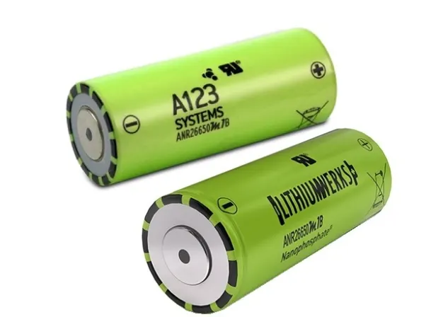
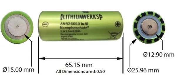
Cell Name - Nano phosphate High Power Lithium Ion Cell.
Model - ANR26650M1-B.
The battery LiFePo4, Battery of A123 System is a high-performance battery. It delivers high power and energy density combined with excellent safety performance and enhance life cycling in a compact and light weight package.
The cell has low-capacity loss and impedance growth over time as well as high usable energy over wide SOC.
The cell can meet end-of-life power energy requirements with minimal pack oversizing.
APPLICATIONS OF THE ABOVE CELL:
- TRANSPORTATION SOLUTION:
It is suitable for Hybrid, plug In Hybrid and battery electric vehicles battery system.
- Passenger Vehicle.
- Commercial Vehicle.
- Off-Highway Vehicles.
- COMMERCIAL SOLUTIONS:
It is a replacement for Lead Acid battery.
- Autonomously guided vehicles (AGVs).
- Industrial robotics and material handling equipment.
- Medical devices.
- IT backup.
- Government Solutions:
It is use for Government services for better reliability.
- Military vehicles.
- Military power grids.
- Soldier power.
- Directed energy.
- GRID SOLUTIONS:
Proven and versatile storage system for Grid.
- Frequency regulation.
- Renewables integration.
- Reserve capacity.
- Transmission and distribution.
The cell ANR26650M1-B is now produced by LithiumWerks in the market is a next generation 26650 cylindrical cell. This versatile lithium-ion cell is suitable for a wide variety of applications and system designs. Proven performance in the toughest conditions, combining durability, reliability, and safety, the ANR26650 cell offers an excellent combination of price-performance.
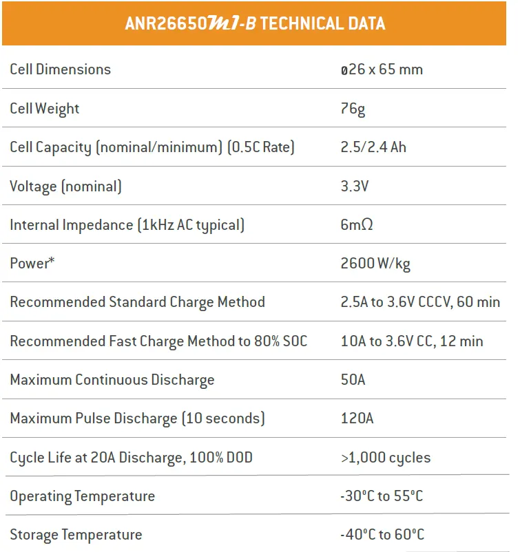
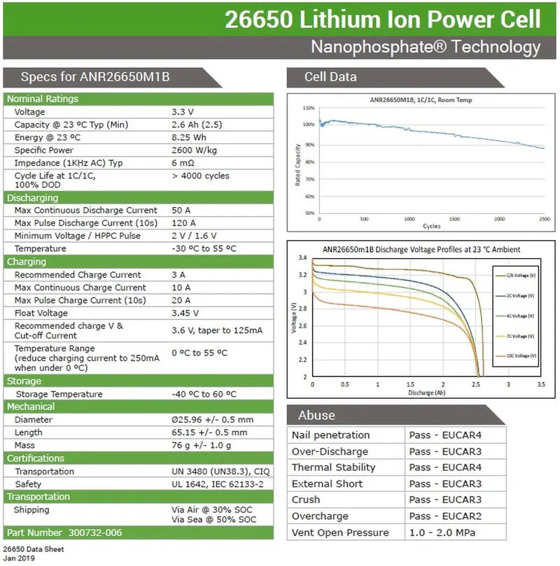
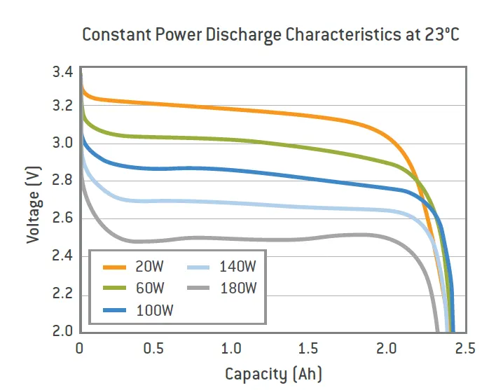
The datasheet screenshots are given below which shows complete specification of Cell ANR26650M1-B.
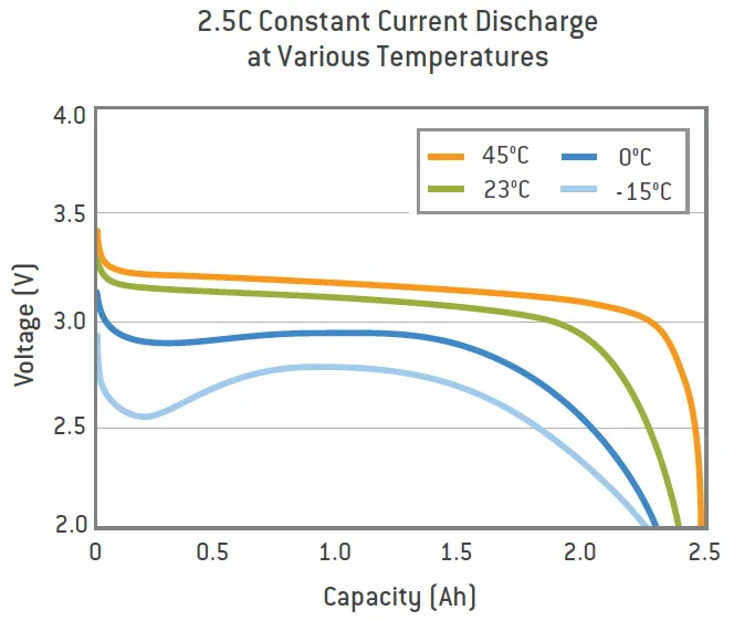
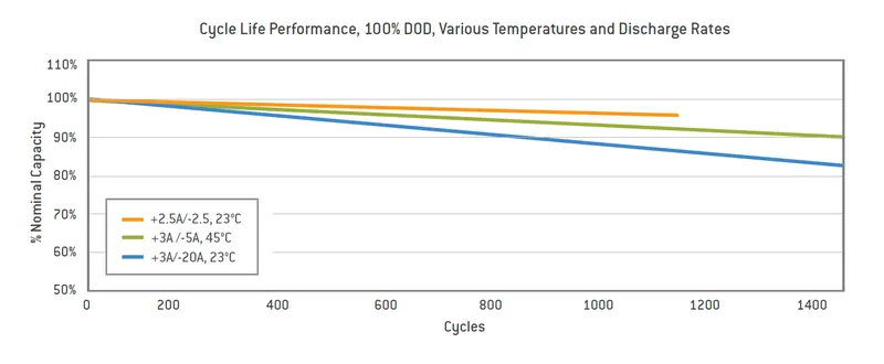
As we know to make the future of mobility green, electrification of Automobile has begun as revolution and Lithium-ion cells are major player in this to produce source of electric power for traction motor and other auxiliary unit of the vehicle.
A high voltage battery pack is one of the most important components of Battery Electric Vehicle. The battery pack of any vehicle should be able to provide the following
- It should provide required power to traction motor.
- It should be able to meet range demand.
- It should be reliable for long time, so life cycle of the battery should be high.
To get a high voltage from lithium-ion cell, cells are arranged in series and parallel to achieve desire voltage, power (KWh) and capacity (AH). Generally, to achieve this a large battery pack is made by arranging several battery modules consisting cell in series and parallel, further these modules are connected in series and parallel arrangements.
BATTERY MANAGEMENT SYSTEM:
A battery management system is electronic device or system that manages a rechargeable battery pack in Electric vehicle or Hybrid Electric vehicle. It protects the battery from operating outside its safe region, Monitor State of Charge, Calculate Data, Reports Data and controls the environment by balancing the battery pack operations.
A BMS is attach to each battery module and a master BMS is connected to Battery pack, which receives data from all the BMS and operates accordingly.
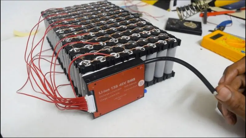
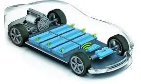
In the above image it can be seen wireless BMS are attach to each battery module and a master wireless BMS collects all data to act accordingly to control battery pack so that battery pack can perform well.
WHY BATTERY MANAGEMENT SYSTEM IS NEEDED:
- For the safety of the operator, must detect unsafe operating conditions and respond.
- To improve the life of battery pack under normal operating condition by advising the dynamic power limits & controlling thermal management system.
- To protect cells being damage due to abuse or failure cases.
- To report user or other devices.
BATTERY MANAGEMENT SYSTEM REQUIREMENTS:
- To sense Voltage.
- To sense current.
- T sense Temperature.
- Contactor control.
- Protection and thermal control
- Charger control.
- Communication and data logging.
- State of Charge, Power and Energy estimation.
- Diagnostic

BATTERY THERMAL MANAGEMENT SYSTEM
- The high battery temperature leads to poor performance, short lifetime, and risk of blasting. Therefore, a BTMS is essential for all battery modules.
- The main purpose of a BTMS is to maintain the battery system in the optimum temperature range and keep uniform temperature variation in the battery modules.
The following figure shows the most used thermal management techniques for battery module.
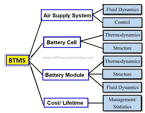
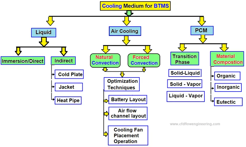
For better adaption to EVs, BTMS must ensure features such as high performance, simplicity, low weight, reduced cost, fast packaging and easy maintenance. Two types of battery cooling systems (BCS) are common which are external or internal. External Battery cooling systems (EBCS) are classified into several different ways
Battery cooling can be categorized based on the method or technique.
To stop Thermal Runaway the compactness of battery pack can be reduced.
Research shows that increasing cell-to-cell spacing for a battery pack from 1 mm to 10 mm, can lead to loss of approximately 1°C.
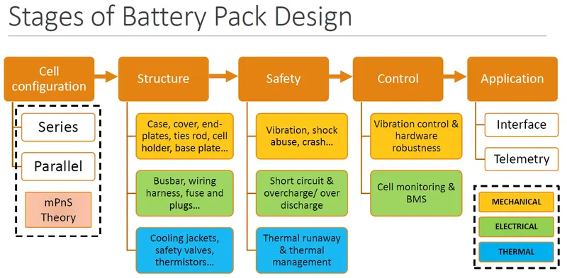
MECHANICAL DESIGN OF BATTERY PACK:
A battery pack must be reliable and robust for safety purpose. A reliable battery pack should be able to address issues relating to
- Thermal Stability.
- Vibration Isolation
- Impact resistance at micro as well as macro level.
- It should minimize thermal and mechanical interaction between different units of battery pack at each level.
A battery pack protection can be designed based on certain critical control factors
- Cell spacer type.
- Number and location of gas exhaust nozzles.
- Battery Cooling System.
- Thickness of insulation coating.
According to the Question I need to design an EV battery pack with capacity 18 KWh.
For that let us consider that a Battery Electric Vehicle needs 300 volts supply from a battery pack. So, Voltage is 300 volts.
1.) Number of cells in series are:
N_S = ( Battery pack voltage (V))/(Nominal Voltage of single cell (V)) = 300/3.3 = 91 Cells
2.) Capacity of Battery Pack is:
(Energy Of Battery Pack (Wh) )/(Battery pack voltage (V)) = 18000/300 = 60 Ah
3.) Number of cells Required in Parallel:
N_p = (Total Required Capacity(Ah))/(Capacity of single cell (Ah)) = 60/2.5 = 24 Cells
4.) RANGE:
Suppose the vehicle consumes 60 Wh Energy per 100 km after considering all the efficiency then the range will be
Range= (Total battery pack capacity(Wh))/(Energy consumed per 100 km(Wh/km)) = 18000/60 = 300 Km.
5.) Total cells required for battery pack:
NS*NP = 91*24 = 2184 Cells.
Capacity of single cell = Nominal voltage of single cell * capacity of single cell
Capacity of single cell = 3.3*2.5 = 8.25 Wh
So, capacity of 2184 cells are
= 2184*8.25 = 18018 Wh = 18.018 KWh.
6.) Gravimetric Energy Density or specific energy density of cell:
(Capacity of single cell (Wh))/(Weight of single cell (Kg)) = 8.25/0.076 = 108.974 Wh/kg
BATTERY PACK DIMENSIONS:
n = Number of cells in series.
C = Clearance at side = 30 mm.
2C = clearance at both side of Length and Breadth
Spacing between 2 cells = 5 mm.
Number of spacing where 91 series cells are arranged = 45.
S = length of total spacing given to 91 cells in series = 45*5 = 225 mm
D = Diameter of cell = 26 mm.
H = Height of cell = 65 mm.
L = Length of Battery pack in (mm).
B = Breath of Battery Pack in (mm).
L = n*D + 2(C) + S = (91*26) + (2*30) + 225 = 2651 mm = 2.651 m.
B = D + 2(C) = 26 + 60 = 86 mm = 0.086 m.
Let us consider this length and Breath of 91 cell in series and let us consider this 1 module then Length and Breath of whole module will be
L = 2.651 m. (As all the series cell makes length of battery pack)
B = 0.086*24 = 2.064 m (24 modules will be connected in parallel so, 24 modules breath will be added).
H = 65 + 10 = 75 mm (10 mm tolerance for extra equipment which is not consider in this calc).
The above Length, Breath and Height are rough estimation of how big can be a battery pack carrying 2184 cells array.
JOINING TECHNOLOGIES FOR LITHIUM ION BATTERY:
Automotive battery packs typically consist of large number of battery cells. These cells must be joined together and assemble with robust mechanical and electrical joints. Joining of battery cells brings several challenges like welding of high conductive and dissimilar materials, multiple sheets joining and varying material thickness combination.
Below are some joining technologies:
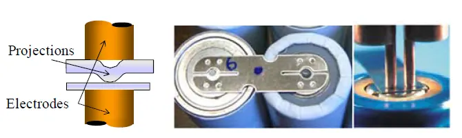
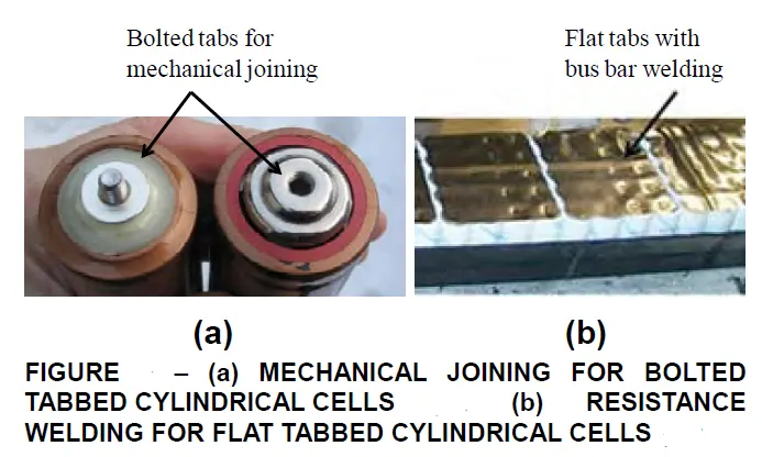
- Resistance Welding – The metal interface that is to be joined provides resistance to the flow electric current. Which in turn produce localized heat which fuse the metal together. The pressure exerted by the electrodes, through which the electrical current flows, holds the workpieces to be welded in close contact.
Resistance welding when applied to battery welding faces a lot of challenges First, lithium-ion batteries use highly conductive materials such as aluminium and copper for electrodes and tabs, which are not best suited to resistance welding. Second welding dissimilar metal by fusion welding produce difficulty due to temperature difference.
To overcome these difficulties Resistance spot projection welding method is use below is the image which showcase how the challenge has been overcame.
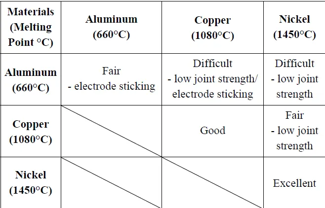
Below is the image for Weldability chart for battery tab materials in resistance welding.
- Laser Welding – Laser welding is a non-contact joining process, that joins multiple pieces of metal through the laser. Due to non-contact welding process, laser welding has a lot of advantages for battery pack manufacturing. Since welding with a low power pulsed Nd: YAG laser produces the smallest heat affected zone and a possibility of multiple sheets joining, laser welding is sometimes considered the optimum welding tool for applications involving lithium-ion batteries. shows an example of laser welding application.
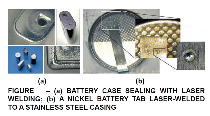
The battery tab here is made of nickel and the case material is stainless steel. In battery tab welding as described weld penetration must be controlled accurately so that the weld nugget does not penetrate into the case
- ULTRASONIC WELDING – Ultrasound welding is done by using high frequency, usually 20KHZ or above. Ultrasonic energy is used to produce oscillating shears which creates solid state bonds between two sheets clamped under pressure. It can be used to join wide range of metal sheets and thin foils.
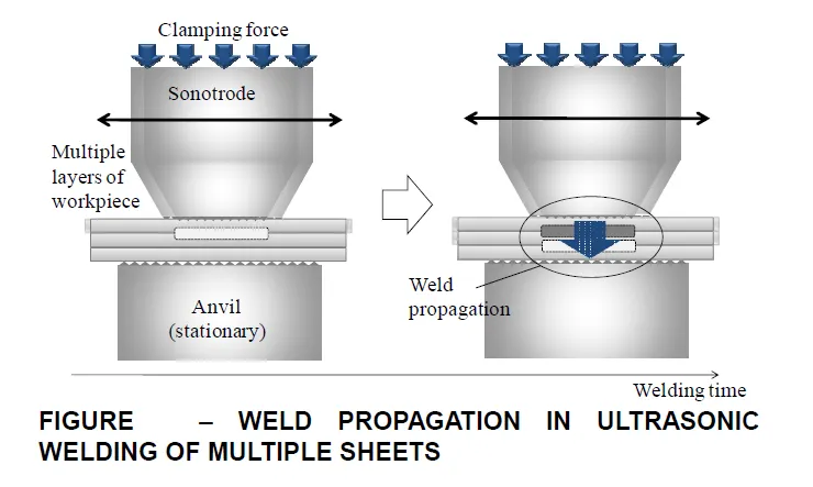
In comparison to traditional fusion welding process, ultrasonic welding has several inherent advantages derived from its solid-state process characteristics.
The advantage of ultrasonic welding are as follows.
- It works fine for dissimilar materials and multiple sheets, which is very important for cell joining and as well as battery tab joining.
- It is an attractive process for battery manufacturing because of its low temperature and relatively good performance for Aluminium, copper and other highly conductive materials.
- The process is environment friendly as it does not use any filler or gas.
The disadvantages of Ultrasonic welding are as follows.
- There is limitation in joint thickness (< 3mm).
- Sensitive to product/process such as surface condition.
- Challenge in joining high strength and high hardness material.
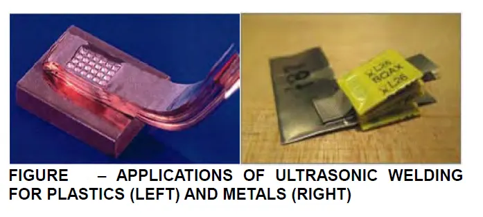
Nevertheless, Ultrasonic welding is considered to be a superior method of welding for battery joining then other welding process discuss above specially for pouch type prismatic battery.
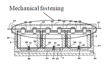
- MECHANICLA JOINING – Mechanical joining is divided in two different groups 1) Fastener and 2) Integral joints
Fasteners include nuts, bolts, screws, pins and rivets.
Integral joints include seams, crimps, snap-fits, and shrink-fits that are designed into the components to be connected. For example, snap-fits are a mechanical joining method where part-to-part attachment is accomplished with locating and locking features
In battery pack manufacturing welding can be effective only for small scale solution or small-scale joining example for connecting multiple battery cells through battery tabs or bus bars.
However, when applied to module-to-module joining, welding may not be appropriate for joining large modules due to battery maintenance and service concerns. So, by using threaded bus bars or metal rods, individual units or modules can be fastened by bolts and nuts. Hence, the major advantage of mechanical joining is the ease of disassembly for maintenance and repair. additionally, mechanical joining is generally performed without heating except maybe in a few particular cases.
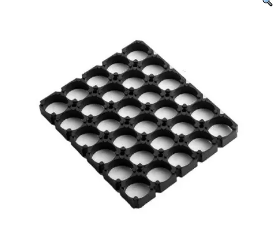
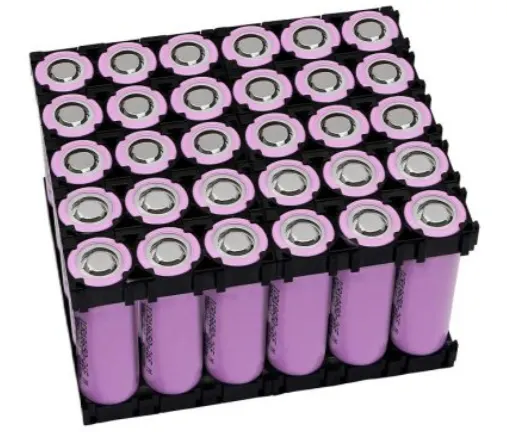
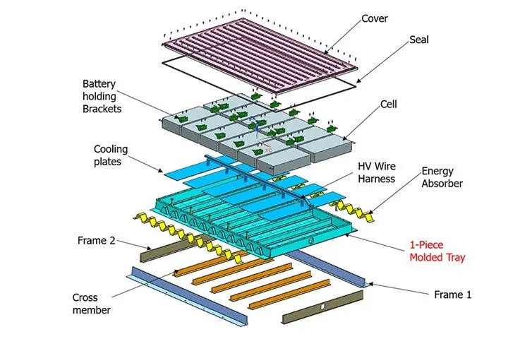
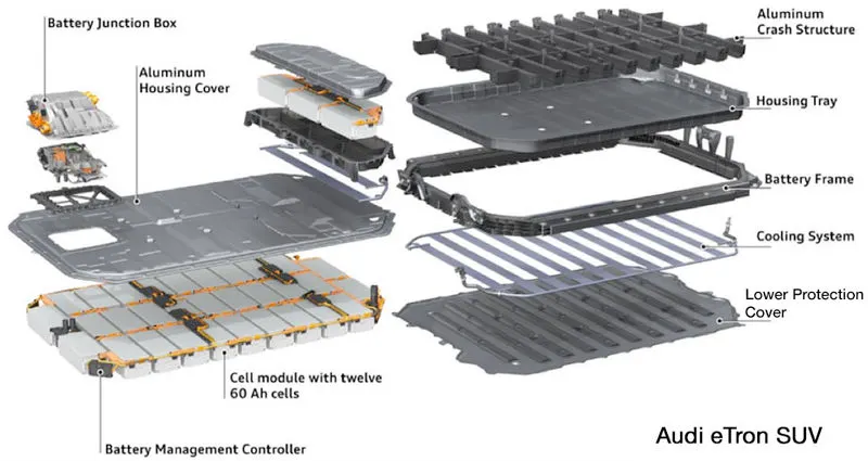
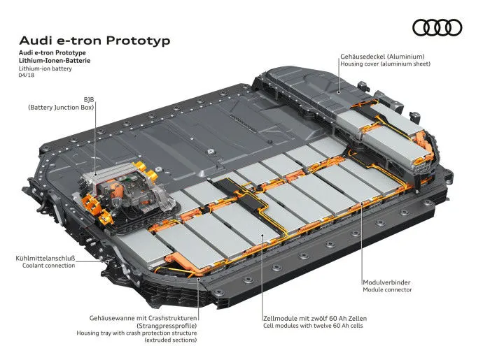
- BATTERY HOLDERS - The main purpose of battery holder is to keep the battery fixed in one place of the module. Battery holder decrease the vibrations and help in proper thermal management of the battery module. Below are the images of battery holder and some battery packs which gives clear idea how important is battery pack and it other parts to keep battery cell safe and reliable.
Related Machine for Cylindrical Cell Making:
|
Process |
Machine |
|
Power Processing |
1.Tube Furnace 2.Muffle Furnace |
|
Power Grinding |
Planetary Ball Mill |
|
Vacuum Mixing |
1.Compact Dual-Shaft Planetary Vacuum Mixer Machine 2.Slurry Vacuum Mixer |
|
Electrode Coating |
Lab Compact Heat Film Vacuum Coating Machine with Doctor Blade |
|
Roll Press |
Heat Rolling Press Machine |
|
Sheet Cutting |
Automatic Slitting Machine |
|
Vacuum Drying |
1.Vacuum Drying Oven 2. Air Convection Drying Oven |
|
Ultrasonic Welding |
Ultrasonic Spot-Welding Machine |
|
Electrode Winding |
Battery Electrode Winding Machine |
|
Spot Welding |
1.Precise Micro Spot-Welding Machine 2. AC Spot Welding Machine 3. DC Spot Welding Machine |
|
Grooving |
Grooving Machine |
|
Glove Box |
Vacuum Glove Box with H2O & O2 Purification System |
|
Electrolyte Injection |
Electrolyte Filling Machine |
|
Electrode Diffusion |
Electrolyte Diffusion & Degassing Machine |
|
Hydraulic Sealing |
Cylindrical Cases Sealing Machine |
|
Battery Analyzer |
5V 3A6A 8Channel Battery Testing Machine |
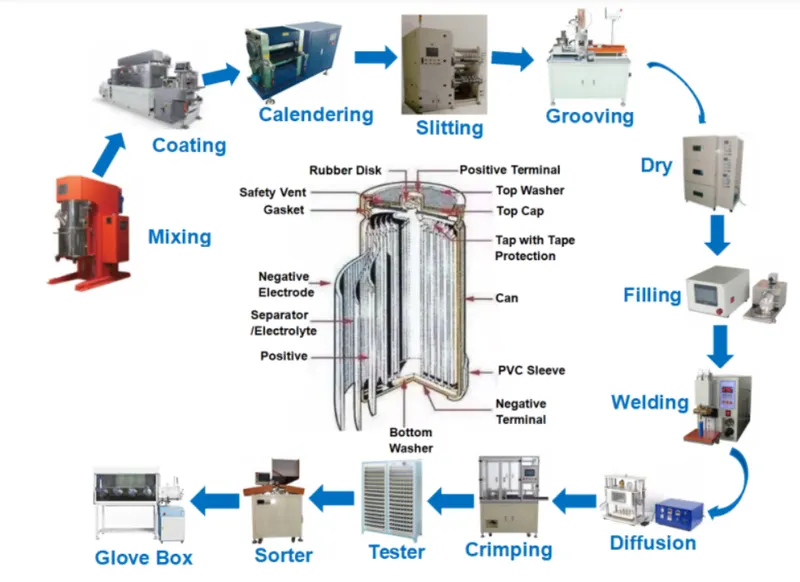
Related Machine for Cylindrical Battery Pack Assembly:
|
Process |
Type |
Product Name |
|
Lithium Battery Sorting |
Manual |
Internal Resistance Tester |
|
Automatic |
5/6/9/11/10/13/22 Channel Battery Sorter |
|
|
Sticking Barley Paper |
Automatic |
Cylindrical Lithium Battery Labelling Insulation Paper Sticking Machine |
|
Spot Welding |
Manual |
1. AC Spot Welding Machine 2. DC Spot Welding Machine 3. Precise Micro Spot-Welding Machine |
|
Automatic (Electric/Pneumatic) |
Single Side Spot Welding Machine Single Side Rotary Head Spot Welding Machine 3. Double Sides Spot Welding Machine |
|
|
PVC Heat Shrink Wrapping |
Automatic |
Heat Shrink Machine |
|
Automatic 18650 PVC Heat Shrink Wrapping Machine for Cylindrical Battery |
||
|
Semi-finished Cell Testing |
Battery Comprehensive Tester |
|
|
Aging |
Battery Charging and Discharging Tester |