Project 1 Mechanical design of battery pack
Aim: Design a mechanical battery pack.
Objective:
Cell: ANR26650M1-B
Battery Pack Capacity: 18 kWh
Prepare a detailed battery pack drawing along with its enclosure. State your assumptions.
Introduction:
As electric vehicles are increasing in the market is gradually increasing, there is considerable growth in the production of lithium-ion batteries. As it is the electrical source for the EV.
10S1P battery
Lithium-ion batteries are popular power sources for cell phones and other electronics but are problematic in extreme heat or cold.
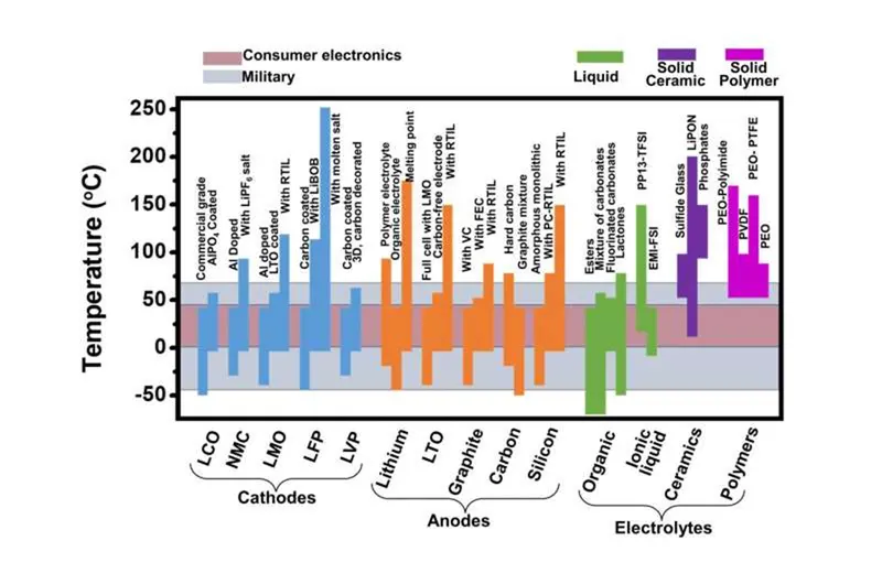
Most batteries will operate, with varying degrees of effectiveness in the 5- 35 °C range so are fine for the autumn and spring operating months, however, if you want a battery that will also operate efficiently in winter and summer you need to understand how temperature has an effect on batteries operating capabilities.
The ambient weather temperatures have a large impact on the performance and on the life of most batteries and unfortunately, it’s a characteristic that isn’t often talked about.
The optimum temperature for most batteries to operate at is around 25°C and this is the temperature all battery testing is performed at. When temperatures vary, either up or down there is an effect on the performance and life of most batteries.
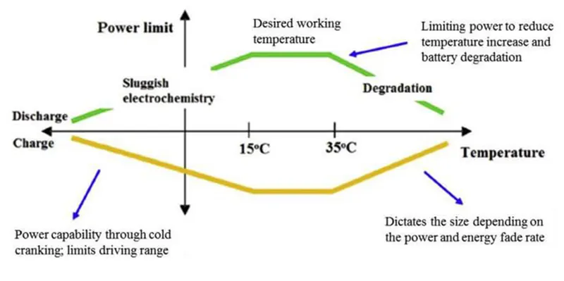
Depending on the chemistry of the battery different batteries will only operate optimally within a limited temperature range, so it’s important to understand this when purchasing or upgrading your battery for energy storage.
When the temperature starts to fall below about 15°C, depending on the battery's chemistry, the electrochemistry of the battery becomes sluggish and doesn’t perform as well. In fact, very few batteries operate below 0°C. This is relevant in many countries in Europe, the USA or Canada but not as relevant in most of Australia.
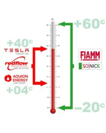
What is relevant to the Australian market is the other end of the scale with the hot weather temperatures, particularly those of 40°C or above. Over 35°C, again depending on the battery chemistry, the battery will not operate and will start to degrade. For this reason, many batteries need to be kept in an air-conditioned environment which adds to the ongoing running costs of the battery and is something that needs to be taken into account when considering the LOC or lifetime cost of a battery. In the past, many installations have installed extra batteries, just to keep the air-conditioning running to keep the batteries cool.
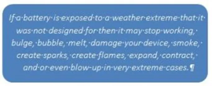
Keeping a battery within its safe operating range is critical in the case of certain battery technologies as some batteries will catch fire if they get too hot. This is one reason those certain batteries have a BMS or battery operating system included to make sure that the battery can’t overheat. However, if this BMS fails or there is no power for an extended period of time there is the possibility of batteries catching fire or exploding. (Just another thing to take into consideration.)
The FIAMM Sodium Nickel Chloride or SoNick batteries are the only batteries that will really work reliably in temperatures over 40°C and these temperatures don’t cause the SoNick battery to deteriorate so won’t have a detrimental effect on the battery’s longevity. This is particularly important in hot areas of Australia or in bushfire prone areas.
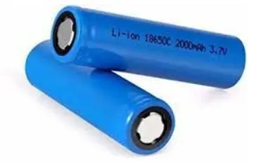
Lithium-ion batteries power the lives of millions of people each day. From laptops and cell phones to hybrids and electric cars, this technology is growing in popularity due to its lightweight, high energy density, and ability to recharge.
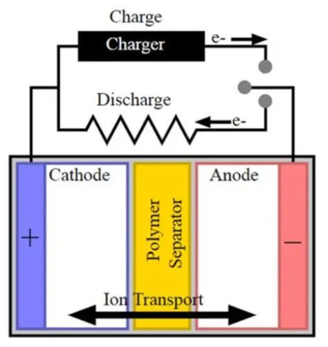
The basic internal structure.
THE BASICS
A battery is made up of an anode, cathode, separator, electrolyte, and two current collectors (positive and negative). The anode and cathode store the lithium. The electrolyte carries positively charged lithium ions from the anode to the cathode and vice versa through the separator. The movement of the lithium ions creates free electrons in the anode which creates a charge at the positive current collector. The electrical current then flows from the current collector through a device being powered (cell phone, computer, etc.) to the negative current collector. The separator blocks the flow of electrons inside the battery.
CHARGE/DISCHARGE
While the battery is discharging and providing an electric current, the anode releases lithium ions to the cathode, generating a flow of electrons from one side to the other. When plugging in the device, the opposite happens: Lithium ions are released by the cathode and received by the anode.
ENERGY DENSITY VS. POWER DENSITY
The two most common concepts associated with batteries are energy density and power density. Energy density is measured in watt-hours per kilogram (Wh/kg) and is the amount of energy the battery can store with respect to its mass. Power density is measured in watts per kilogram (W/kg) and is the amount of power that can be generated by the battery with respect to its mass. To draw a clearer picture, think of draining a pool. Energy density is similar to the size of the pool, while power density is comparable to draining the pool as quickly as possible.
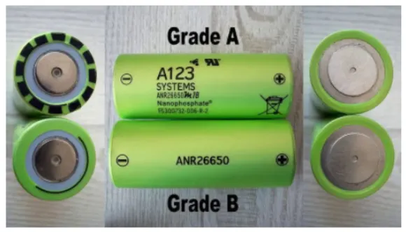
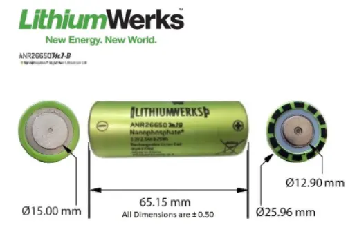
Nanaophospate high Poer Lithium Ion Cell ANR26650M1-B
A123's high-performance Nanophosphate lithium iron phosphate (LiFePO4) battery technology delivers high power and energy density combined with excellent safety performance and extensive life cycling in a lighter weight, more compact package, our cells have a low capacity loss and impedance growth over time as well as high usable energy over a wide sate of charge (SOC( range, allowing our systems to meet end-of-life power and energy requirements with minimal pack oversizing.
Applications of the battery.
There are various applications of Lithium-ion cells
1. Commercial Solutions
This is a large-scale application for the battery where high power is required.
- Datacenter UPS
- Telecom backup
- IT backup
- Autonomously guided vehicles
- Industrial robotic and material handling equipment
2. Government Solutions
- Military vehicles
- Military power grids
3. Grid Solutions
- frequency regulation
- Renewable integration
- Reverse capacity
- Transmission and distribution
4. Transportation Solutions
- Plug-in hybrid vehicles, hybrid cars, electric vehicles
- Commercial vehicles
- Off-highway vehicles
- Passenger vehicles
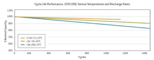
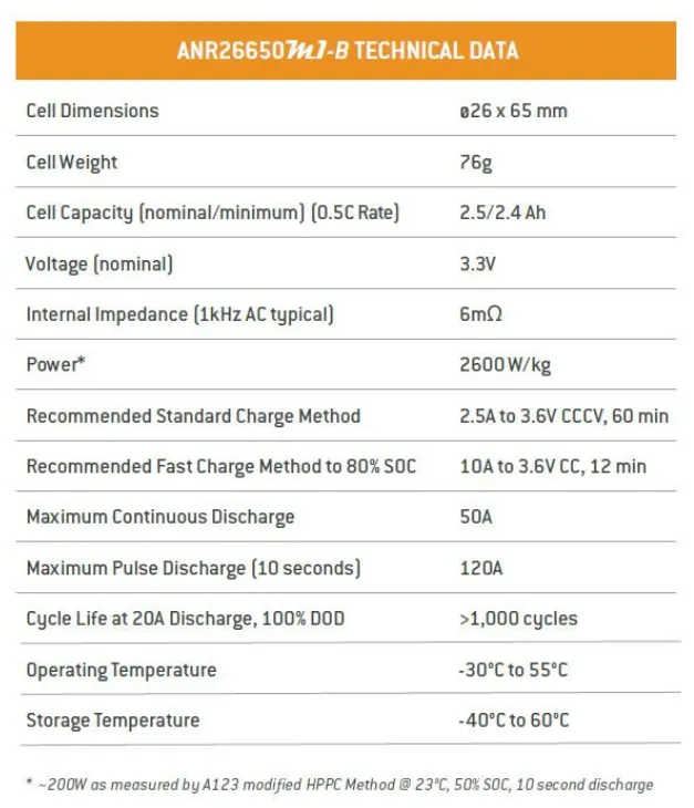
The performance of the cell is given in the datasheet that is referred to for this project.
These images show the power discharge, current discharge, and the life cycle of the cells used for the battery pack.
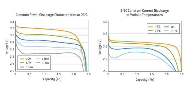
Here you can see the voltage capacity of the battery for different power ratings.
Design Calculation
All the parameters of this calculation are taken from the datasheet.
Procedure for the Calculation:
The capacity of the battery pack is set to be 18kWh.
For making a high voltage battery pack many cells are arranged in a particular pattern and sequence to improve the voltage and the power rating.
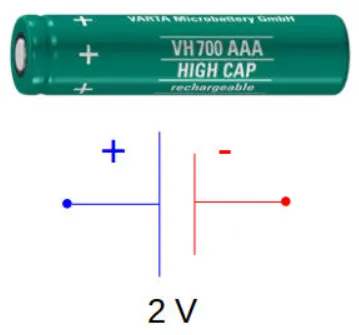
Individual battery cells may be grouped in parallel and/or series as modules. Further, battery modules can be connected in parallel and/or in series to create a battery pack. Depending on the battery parameters, there may be several levels of modularity.
The total battery pack voltage is determined by the number of cells in series. For example, the total (string) voltage of 6 cells connected in series will be the sum of their individual voltage.
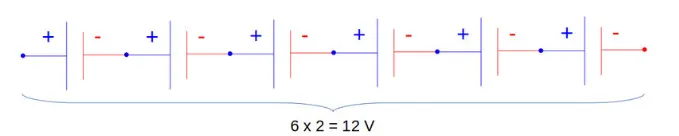
In order to increase the current capability of the battery capacity, more strings have to be connected in parallel. For example, 3 strings connected in parallel will triple the capacity and current capability of the battery pack.
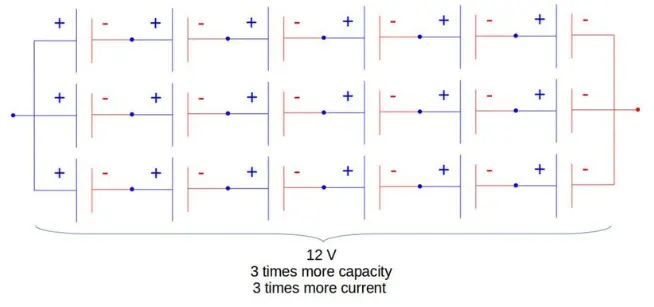
Now for calculating our required battery pack on the cell manufacture data provided.
The calculation for the battery pack is as follows:
1. Volume of each cell
Cylindrical volume Vc [m3]
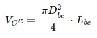
From the datasheet we have Dbc = 26mm = 0.026m and Lbc = 65mm = 0.065m
Therefore, VCc = π * 0.0252 * 0.065/4 = 3.5 * 10-5 m3
The volume of each cell is 35 mm3
2. Battery Cell Energy
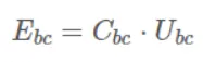
we have,
Cbc = 2.5 Ah
Ubc = 3.3 V
Substituting the values in the above equation we get
Ebc = 2.5 * 3.3 = 8.25 Wh
3. Battery cell energy density
- Volumetric energy density
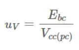
Substituting the value
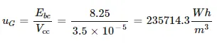
- Gravimetric energy density
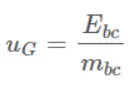
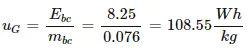
Substituting the above-calculated values in the equation, we get,
4. Total number of the battery pack
The total energy of the battery pack which is required is given as 18 kWh
Ebp = 18000Wh
5. Number of cells connected in series
It is calculated by dividing the nominal battery pack voltage Ubc [V] by the voltage of each battery cell Ubc [V]. The number of strings must be an integer. Therefore, the result of the calculation is rounded to the higher integer.
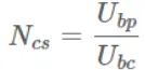
Let us assume that the battery pack voltage which is required to be 330V and the nominal voltage of the battery as per the datasheet is given as 3.3V.
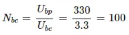
The total number of cells in series is 100
6. Energy Content of a string
The product between the number of battery cells connected in series and the energy of a battery cell
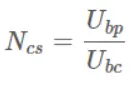
Ebs = Ncs * Ebc = 100 * 8.25 = 825 Wh
7. Number of strings in the battery pack
It is calculated by dividing the battery pack's total energy Ebp [Wh] by the energy content of a string Ebs [Wh]. The number of strings must be an integer. Therefore, the result of the calculation is rounded to the higher integer.
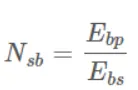
Substitute the above value
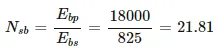
All the 22 strings will be connected in parallel
8. Battery pack Capacity
It is calculated as the product between the number of strings Nsb [-] and the capacity of the battery cell Cbc [Ah].
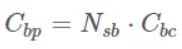
Cbp = Nsb * Ccb = 22 * 2.5 = 55Ah
9. Total number of cells of the battery pack
It is calculated as the product between the number of strings Nsb [-] and the number of cells in a string Ncs [-].
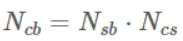
Ncb = Nsb * Ncs = 22 * 100 = 2200
The total number of cells required for the design pack is 2200.
10. Mass of the battery pack
It is the product of the total number of cells Ncb [-] and the mass of each battery cell mbc [kg].

mbp = Ncb * mbc = 2200 * 0.076 = 167.2 kg
11. Volume of the battery pack
It is the product of the total number of cells Ncb [-] and the mass of each battery cell Vcc(pc) [m3]. This volume is only used to estimate the final volume of the battery pack since it does not take into account the auxiliary components/systems of the battery.
12. String peak Current
Is the product between the peak C-rate of the battery cell C-ratebcp [h-1] and the battery cell capacity Cbc [Ah].
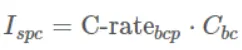
From the datasheet, the battery pack C-rate is 24 and the nominal capacity is 2.5Ah.
Ispc = 24 * 2.5 = 60A
13. Battery pack peak power
Is the product between the string peak current Ispc [A] and the number of strings of the battery pack Nsb [-].

Substituting the above values
Ibpp = 60 * 22 = 1320 A
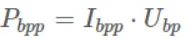
14. Battery pack peak power
Is the product between battery pack peak current Ibpp [A] and the battery pack voltage Ubp [V].
Substituting the above values
Pbpp = 1320 * 330 = 435600 W = 435.60kW
15. String continuous current
It is the product between the continuous C-rate of the battery cell C-ratebcc [h-1] and the battery cell capacity Cbc [Ah].
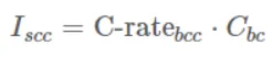
From the datasheet, the battery pack continuous C-rat is 10 and the nominal capacity is 2.5 Ah.
Iscc = 10 * 2.5 = 25 A
16. Battery Pack Continuous Current
It is the product between the string continuous Iscc [A] and the number of strings of the battery pack Nsb [-].
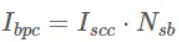
Ibpc = 25 * 22 = 550 A
17. Battery Pack Continuous Power
It is the product between the string continuous Ippc [A] and the battery pack voltage Ubp [V].
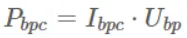
Pbpc = 550 * 33 = 181500 W
The battery pack's continuous power will be 181.5 kW
All the above parameters that are calculated are in the table below.
| Manufacture |
A123 - Systems |
| Number of cells in the string | 100 |
| String Energy | 825 Wh |
| Number of string | 22 |
| Battery Pack Energy | 55 Ah |
| Total Number of Cells |
2200 |
| Battery Pack Mass | 167.2 kg |
| Battery Pack Volume | 0.077 m^3 |
| Battery Pack Peak Current | 1320 A |
| Battery Pack Peak Power | 435.6 kW |
| Battery Pack Continuous Current | 550 A |
| Battery Pack Continuous Power | 181.5 kW |
Battery dimensions:
1. Length of casing length = number of cells * (cell diameter + margin at both sides of cells) + clearance at side
L = 100 * (26 + 4) + 60 = 3060 mm
2. Breadth of the casing (B)
Breadth = number of cells * (cell diameter + margin at both side of cell) + clearance at side
B = 22 * (26 + 4) + 60 = 720 mm
3. Height of casing (H)
Height = Height of cell + margin for wiring
H = 65 + 35 = 100 mm
Assembly of the battery pack
Component of the battery pack
- 2200 cells
- Nickel strip
- PVC heat sink film
- Spot welder
- Connected
- Cell holder
- Solder
Step 1-
The first step is to start snapping the square cell holder together. One can use the cell terminal block but it will take more space than a hexagonal block.
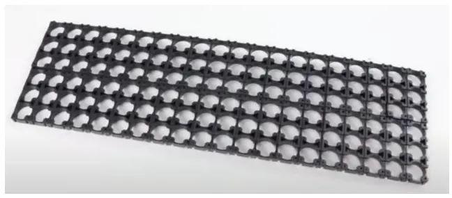
This is the cell holder block

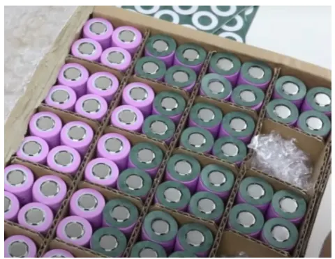
This image shows the insulate gasket
Step 2-
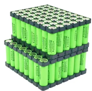
Placing the cells in the holder matrix. Place all the cells in the holder and put the second holder in the place.
Step 3-
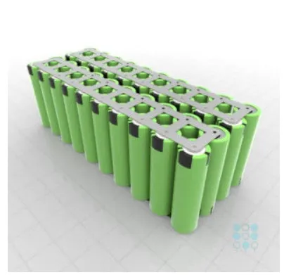
Now we will be connecting the cells with nickel strips using the spot welding process. The series connection will be made by connecting the positive terminal of the cells to the negative terminal. The parallel connection will be made by connecting the same terminal.
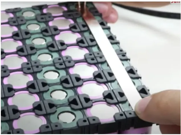
Connecting the complete matrix of the cell together.
Step 4-
Connecting the heat sink to the battery pack
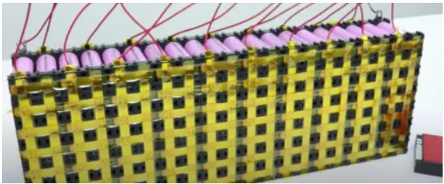
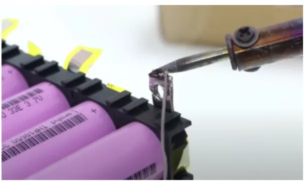
Now we will be soldering the battery wire
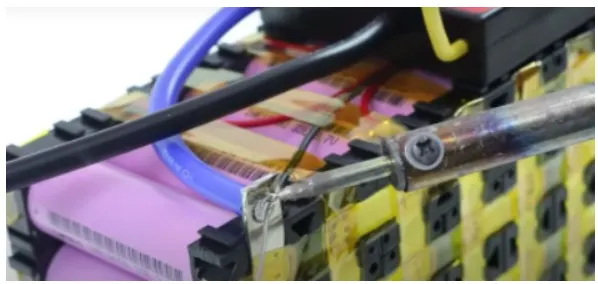
Now the internal structure of the battery pack is assembled and all the terminals are connected as per the connections.
Step 5-
Connect the balancing wire pin to the battery management system.
Step 6-
After the battery management system, the next and final step is to place the enclosure for the battery pack.
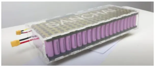
This is the final battery pack model created.
CONCLUSION
The design calculation for the battery pack was carried out and calculated and a table has been made for the same. The steps involved in the making of the battery pack have been listed.
Thank you...