Mechanical Design of a Battery Pack
OBJECTIVE:
To Design the Base/Bottom Plate of a Battery Pack for an EV application given the following conditions:
- Battery Pack Capacity: 18 kWh
- Cell Model: ANR26650M1-B
SOLUTION:
#1) Importance of Mechanical Design and Packaging of Battery Pack for EV Application:
- Safety: Battery Packs possess a great degree of Safety Concern and are prone to Failure. Hence a Robust Mechanical Design and Packaging is necessary to mitigate the issues related to Safety and Battery Pack Failure. The Safety Concerns and Battery Pack Failure Concerns pertaining to the Mechanical Design are in general due to Adverse Road Conditions. These Adverse Road Conditions can lead to Continuous Transmission of Mechanical Vibrations, Exposure to High Impact Forces and Thermal Runaway. Also, if an EV moves through a Waterlogged Area, then the Water can move inside into the Battery Pack and can lead to Fire (as Water (Not Distilled) is a conductor of electricity) if the Mechanical Design of the Battery Pack & its Packaging is improper. Hence even in Extreme Environment & Road Conditions, the Structural Integrity of the Battery pack has to be maintained.
- Cost, Productivity & Reliability: From the Consumer/Customer point of View, the Cost of the Battery Pack has to be minimum while maintaining the Structural Integrity of the Battery Pack and should also be Reliable and Productive. Productivity means the ease with which the Battery Packs can be assembled/disassembled for Service, Recycling or Manufacturing. If the Battery Pack is less productive, assembling/disassembling the Battery Pack will be very difficult which in turns results in High Cost for assembling/disassembling the Battery Pack. The Assembling/Disassembling of the Battery Pack includes use of Mechanical, Electrical, Electronic & Thermal Components and its Effective Placement/removal at/from its respective positions.
The Battery Pack should be reliable so that Battery Performance is maintained at the optimum level and Battery Life lasts as per the Specifications mentioned in the Battery Pack Datasheet or the EV Datasheet. To fulfil the requirements as specified in the Catalogue of the EV/Battery Pack, Proper Mechanical Design & Packaging is necessary.
- Compactness: The Mechanical Design of the Battery Pack should be such that it occupies minimum volume and provide maximum energy output i.e., the Energy Output per unit mass (Wh/kg) of the Battery Pack should be as high as possible.
- Lightweight: Proper Mechanical Design of the Battery Pack is needed to ensure that the Battery Pack is as lightweight as possible by ensuring Proper Placement of the Battery Pack components (like Bus Bars, Casings, Holders) in proper positions. This is necessary because more the mass of the Battery Pack, more the Energy Requirement/Demand to run the Vehicle.
#2) Assumptions for my Mechanical Design of the Battery Pack:
- Apart from the Self-Weight of the Cell(s), no other Forces are assumed to be acting on the Battery Pack.
- The EV is assumed to be in a state of Rest.
- The Cells in the Battery Pack are thermally isolated.
- The Cells in the Battery Pack are all considered to be fully Charged initially before use.
- The Average Range for the EV is assumed to be 185 km.
- The DoD (Depth of Discharge) of the Cells is considered to be 80%.
- The Energy Consumed by the Auxiliary System of the Vehicle is assumed to be 2 Wh/km.
- The Battery Capacity to be assumed for this problem is 18 kWh. However, for Precise Calculation & Results, the Battery Capacity is assumed to be 18.476 kWh.
- The Nominal Voltage of the Battery Pack is assumed to be 185 Volts.
- The Spacing between Cells in the Battery Pack is assumed to be 5 mm.
- The Clearance between 2 adjacent Modules is assumed to be same as the Space between 2 adjacent Cells i.e., 5 mm.
- The Height of the Battery Pack is assumed to be same as the Height of the Cell i.e., 65 mm.
#3) Building the Battery Pack:
Given:
As mentioned in the Objective, the Battery Pack has to be built using A123 Systems’ ANR26650M1-B Cells and the Pack Capacity of the Battery has to be 18.476 kWh.
The Energy consumed by the Battery till DoD (Depth of Discharge) of 80% is 18.476 kWh.
As per the Specification Sheet of ANR26650M1-B Cell Model, the Cell Data for the Battery Pack are as follows:
|
Nominal Cell Capacity |
2.5 Ah |
|
Minimum Cell Capacity |
2.4 Ah |
|
Cell Voltage (Nominal) |
3.3 V |
|
Internal Impedance (1 kHz AC Typ) |
6 mΩ |
|
Specific Power Output |
2600 W/kg |
|
Recommended Std. Charge Method: |
2.5A to 3.6V CCCV, 60 minutes (1C Rate) |
|
Recommended Fast Charge Method to 80% SOC from 100% SOC |
10A to 3.6V CC, 12 minutes (5C Rate) |
|
Maximum Continuous Discharge Current |
50A |
|
Cycle Life at 20A Discharge, 100% DoD |
>1000 Cycles |
|
Operating Temperature |
-30°C to 55°C |
|
Storage Temperature |
-40°C to 60°C |
|
Mechanical Data: |
|
|
Diameter |
26 mm |
|
Length |
65 mm |
|
Cell Weight |
76 grams |
|
Cell Type |
Cylindrical |
To Find:
- Average Energy Consumed per km by the Vehicle Drivetrain.
- Configuration of Cells in the Battery Pack (Series-Parallel Combination of Cells).
- Configuration of Cells in Each Module of Battery Pack.
- Number of Cells/Module.
- Cell Weight, Battery Pack Weight and Module Weight.
- Length & Width of Battery Pack.
- Mechanical Design of Base Plate: Material Selection & Thickness of the Base Plate based on the Self-Weight of the Battery Pack.
Answer:
- Average Energy Consumed by the Battery Pack:
Total Energy Consumed by the Battery on 80% DoD to cover a distance of 180 km = 18476 Wh
Total Energy Consumed by the Battery on 100% DoD to cover a distance of 180 km = (18476 * 0.8)/1
Total Energy Consumed by the Battery on 100% DoD to cover a distance of 180 km = 14780.8 Wh
Average Energy Consumed by the Battery Pack to cover a distance of 180 km = 14780.8/180 = 82.11 Wh/km.
- Configuration of Cell(s) to make the Battery Pack:
Number of Cell(s) in Series:
= Nominal Voltage of the Battery Pack/ Nominal Voltage of Each Cell
= 185 V/3.3 V
= 56.06
≈ 56 Cells
Therefore, the Number of Cells in Series Configuration in the Battery Pack is 56.
Number of Cell(s) in Parallel:
= 40 Cells
Therefore, the Number of Cells in Parallel Configuration is 40.
Battery Pack Configuration, Total Number of Cells, Module Configuration, Number of Cells in Each Module:
- Therefore, the Battery Pack Configuration is 56S 40P.
- Total No. of Cells in the Battery Pack = 56 X 40 = 2240 Cells.
- Module Configuration = 8S 4P. This Module Configuration as my aim for arranging the Cell(s) was such that the Module wouldn’t be too long and wide.
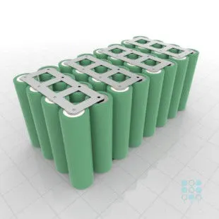
8S 4P Cell Configuration
- Total No. of Cells in Each Module = 8 X4 = 32 Cells.
- Total No. of Modules required = 2240/32 = 70 Modules.
Cell Weight, Module Weight and Battery Pack Weight:
- The Weight of Cell is 76 gm.
- There are 8 X 4 = 32 Cells in the Module. Therefore, the Weight of each Module is (32 X 76) gm = 2432 gm = 2.432 kg.
- There are 56 X 40 = 2240 Cells in the Battery Pack. Therefore, the Weight of the Battery Pack is (32 X 2240) gm = 71680 gm =71.680 kg.
Length & Width of the Battery Pack:
The ANR26650M1-B Cell Model has 26 mm as its diameter. The Cell Configuration is 56 S 40 P. In between the Cells, the spacing is assumed to be 5 mm. Therefore, the Length & Width of the Battery Pack is calculated considering the Diameter of Cell(s) and assuming the spacing between the Cell(s) is 5 mm.
The Length of the Battery Pack is calculated by taking the Series Configuration of the Battery Pack as it has the more no. of Cell(s) than the Parallel Configuration.
Therefore, the Length of the Battery Pack = [(No. of Cells in Series Configuration) X (Diameter of Each Cell)] + [(No. of Spaces between the Cells along the Series Configuration of Battery Pack) X [Spacing given between 2 Consecutive Cells]]
Length of the Battery Pack = [56 X 26] + [55 X 5] mm
Length of the Battery Pack = 1731 mm = 1.731 m.
The Width of the Battery Pack is calculated by taking the Parallel Configuration of the Battery Pack as it has the lesser no. of Cell(s) than the Series Configuration.
Width of the Battery Pack = [56 X 40] + [39 X 5] mm
Width of the Battery Pack = 1040 + 195 = 1235 mm = 1.235 m.
Therefore, the Area over which the Battery Pack is kept is (1731 X 1235) mm2 = 2137785 mm2 = 2.137785 m2
Base Plate Design:
To Prepare a Mechanical Design of the Battery Pack, we need to know the Forces acting on the Mechanical Components of the Battery Pack.
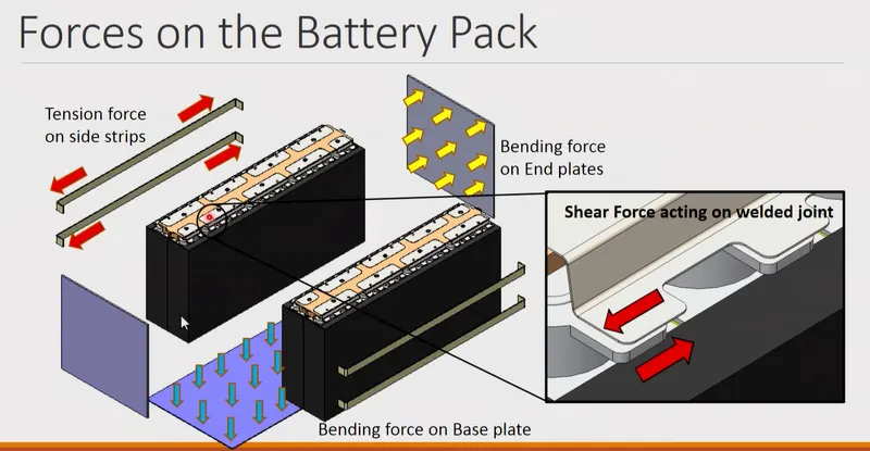
The Above Picture represents the Forces exerted by the Battery Pack acting on the surrounding Mechanical Components of the Battery Pack.
The Approach to the Design of the Base Plate is to understand the Forces/Load(s) acting & its effect and select the Material according to the limits of Design.
The Length & Width of the Base Plate is assumed to be same as the Length & Width of the Battery Pack.
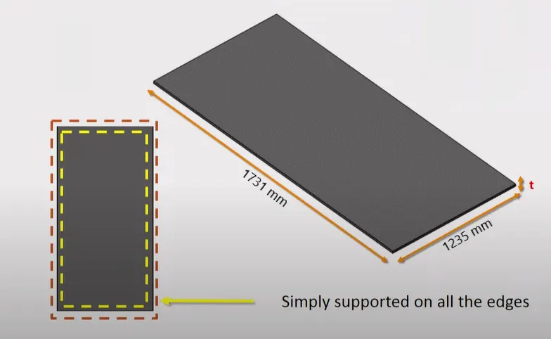
Base Plate Dimesnions. The Thickness of the Base Plate is to be found out according to the Material & the Forces acting on the Base Plate
The Thickness of the Base Plate has to be determined and it depends on the Force(s) acting on the Base Plate and the Material of the Base Plate.
Considerations for designing the Base Plate:
- The Base Plate is simply supported on all edges.
- The Weight of the Battery Pack is considered to be uniformly distributed on the Base Plate.
- The Base Plate is a continuous Rectangular Plate with a constant thickness.
Material Selection for the Base Plate:
- The Material for the Base Plate is selected using the Ashby Methodology. In this Method, the Variables responsible for the Design of the Bottom Plate are considered and the Boundary Conditions are established for this Variables.
- After Establishing the Boundary Conditions for this Variables, the Objective Function is defined which represents the Primary Objective for the Design of the Bottom Plate. This Objective Function can be to Maximize/Minimize the Primary Variables responsible for the design of the Bottom Plate.
- Additionally, a Secondary Objective Function can also be defined in case in order to eliminate Options in case Multiple Options satisfy the Primary Objective Function and the Boundary Conditions of Variables necessary for the design of the Bottom Plate.
- Applying the Ashby Methodology, the Material Index for the Bottom Plate is calculated:

Where M -> Material Index
Cm -> Cost of Material
ρ -> Density of Material
E -> Elastic Modulus
Maximizing the Material Index (M) will ensure that the thickness is minimum.
- After screening through various Relevant Materials, 2 Materials are selected which satisfies the Objective Function and the its required Constraints (Boundary Conditions): Mild Steel & 6061 Aluminium Alloy.
|
Material Property |
Mild Steel |
Aluminium 6061 |
|
Young’s Modulus |
210 GPa |
68.9 GPa |
|
Cm (Cost of Material) |
Rs. 34/kg |
Rs. 280/kg |
|
Density |
7.85 gm/cc |
2.7 gm/cc |
|
Material Index |
21.8 X 10⁻³ |
5.34 X 10⁻³ |
Among the 2 materials, Mild Steel has the higher Material Index.
- Relevant Properties Information required for finding out the Thickness of the Bottom/Base Plate:
|
Property of Material Chosen |
Mild Steel Property Value |
|
Young’s Modulus |
210 GPa |
|
Max. Yield Strength |
350 MPa |
|
Poisson’s Ratio |
0.3 |
Base Plate Calculations:
- For calculating the thickness of the Base Plate, the Maximum Deflection of the Base/Bottom Plate on application of the Self Weight of the Battery Pack needs to be known.
- Also, the Value of the thickness of the Bottom Plate obtained by the necessary calculations is verified by calculating the Maximum Bending Stress on the Bottom/Base Plate due to the Self Weight of the Battery Pack and ensuring that the Maximum Bending Stress obtained lies within the Maximum Yield Strength/Allowable Bending Strength of the Material used (Mild Steel).
- Formulas for obtaining the thickness of the Base/Bottom Plate & the Maximum Stress generated in the Base/Bottom Plate for the obtained Thickness Value:
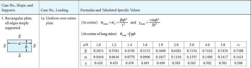
In the above formulas, a & b represents the length & width of the Base Plate respectively. Thus
a = 1731 mm = 1.731 m
b = 1235 mm = 1.235 m
Therefore, (a/b) = (1731/1235) = 1.4016
According to the Reference Sheet, for (a/b) = 1.4016 ≈ 1.4
α = 0.0770
β = 0.4530
In the formulas, q represents the Pressure acting on the Base/Bottom Plate due to the Self-Weight of the Battery Pack.
q = 3.2892 X 10⁻⁴ N/mm2
q = 3.2892 X 10⁻⁴ MPa
q = 3.2892 X 10² Pa = 328.92 Pa
Therefore, the Pressure acting on the Base/Bottom Plate due to Self-Weight of the Battery is 328.92 Pa.
- Calculating thickness of the Base/Bottom Plate & the Maximum Stress generated in the Base/Bottom Plate for the obtained Thickness Value:
Thickness of the Base/Bottom Plate is calculated by assuming the Maximum Deflection of the Bottom to be 1 mm in the downward direction.
Therefore, ymax = -1 X 10⁻³ m
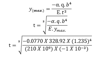
t = 0.00654 m
=> t = 6.5465 mm.
Calculating the Maximum Bending Stress on the Base/Bottom Plate for thickness = 6.5465 mm:
σ max. = 5302865.4097 Pa
σ max. = 5.3028 MPa
Therefore, the Maximum Bending Stress acting on the Base Plate due to the Self-Weight of the Battery Pack is 5.3028 MPa.
The Yield Strength/Allowable Bending Stress of Mild Steel (Material used for Base Plate) is 350 MPa.
The Maximum Bending Stress is a lot less than the Yield Strength/Allowable Bending Stress of Mild Steel (Material used for Base Plate).
The Value of 5.3028 MPa as the Maximum Bending Stress is obtained on assuming the Maximum Deflection of the Base Plate due to the Self-Weight of the Battery Pack to be 1 mm. If I had assumed the Maximum Deflection of the Base Plate to be even greater than 1 mm (for example 1.3 or 1.6 mm), then the thickness of the Base Plate would come out to be lesser than 6.5465 mm and then the Maximum Bending Stress would have increased but would still have been within the Yield Strength of Mild Steel. This can be done by the Designer if there is a need felt to reduce the thickness of the Battery either due to Space Constraints or due to Material Shortage or unavailability of a 1 mm thickness Rectangular Plate.
REFERENCES:
- Behaviour of Lithium-Ion Batteries in Electric Vehicles: Battery Health, Performance, Safety, and Cost by Gianfranco Pistoia and Boryann Liaw
- Roark’s Formulas for Stress and Strain by Richard G. Budynas and Ali M. Sadegh
- https://datasheetspdf.com/pdf/1424845/A123Systems/ANR26650M1-B/
-
Design and Optimization of Battery Housing in Electric Cars ->Master’s thesis in Product Development by Abhishek Bala & Meher Chaitanya Kamaraju