Project 1 Mechanical design of battery pack
Objective:
Here we need to design a 18KWh battery pack. Based on this power requirement, We need to see how many cells are required in series and parallel connections. To arrange the cells in an eclosure, What should be the dimensions of the enclosure. How the cells connections are to be made (material and method).
Introduction:
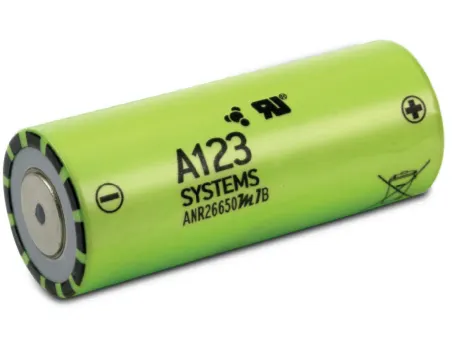
Cell: ANR26650M1-B is used in this project. It is Lithium iron phophate (LiFePO4) type of chemistry cell. This cell is manufatured by A123 systems. It delivers high power and energy density combined with excellent safety performance and extensive life cycling in a lighter weight, more compact package. It is a Cylindrical type of cell with a diameter of 26 mm and a length of 65 mm. Further cell parameters are shown in the figure below,
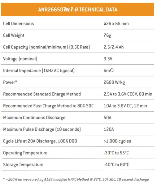
Figure-1 Cell technical data
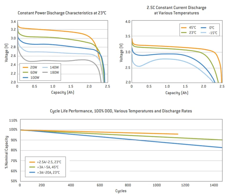
- Cell discharge charateristics and cycle life are shown in the figure below,
Battery pack drawing:
Assumptions:
- Total battery pack voltage is considered as 300 V.
Given:
Nominal cell voltage = 3.3V
Rated cell capacity (0.5 C rate) = 2.5 Ah
Procedure:
Cell energy capacity (Wh) = Nominal voltage * Rated cell capacity = 3.3*2.5 = 8.25
Required capacity of the battery pack (Wh) = 18000
Therefore,
Number of cells required to achieve this power requirement = 18000/8.25 = 2182 cells, we use 2184 cells
If total voltage of the battery pack is considered to be 300V,
Number of cells in Series connection = 300/3.3 = 91 cells
Number of cell is Parallel connection = 2184/91 = 24 cells
Final configuration of the battery pack is 91S24P
Weight of the battery pack = number of cells* weight of each cell = 2184*0.076 = 165.98 Kg
Enclosure design
Assumptions:
- Gap between cells is 3 mm
Given:
Cell diameter = 26 mm
Cell length = 65 mm
Procedure:
Total cells in series = 91
Total cell is parallel = 24
Length of the battery pack = number cells in series * ( diameter of cell + clearance) = 91*(0.026 + 0.003) = 2.639 m
Width of battery pack = number of cells in parallel * ( diameter of cell + clearance) = 24*(0.026 + 0.003) = 0.696 m
Area of battery pack = 2.639 * 0.696 = 1.836 m^2
Volume of enclusure = area* (height of cell+clearance) = 0.124 m^3
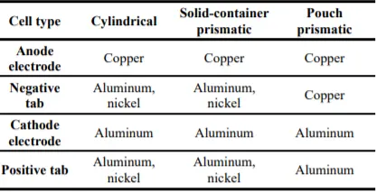
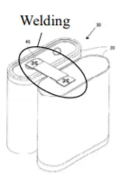
In current automotive lithium-ion battery manufacturing, different sizes and shapes of cells are being manufactured and are subsequently assembled into packs of different configurations. An automotive battery pack typically consists of a large number of battery cells, sometimes several hundreds, even thousands, to meet desired power and capacity needs. Several cells are usually joined together to form a module. There are tens of modules in a battery pack. As a result, a significant amount of joining such as welding is needed to deliver electricity in a battery pack. It is not easy to join such a large number of battery cells because of the difficulty with welding multiple layers of thin, highly conductive and dissimilar materials, with 100% reliability. This section reviews joining technologies that are currently used in battery manufacturing (i.e., resistance welding, laser welding, ultrasonic welding and mechanical joining), and discusses manufacturing issues with regard to the joining of lithium-ion batteries.
Resistance welding:
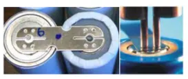
Resistance welding relies on the electrical resistance at the metal interface to cause a localized heating and fusion of materials. The pressure exerted by the electrodes, through which the electrical current flows, holds the workpieces to be welded in close contact before, during, and after the welding cycle. However, resistance welding has many challenges when applied to battery welding. First, lithium-ion batteries use highly conductive materials such as aluminum and copper for electrodes and tabs, which are not best suited to resistance welding. Aluminum and copper (i.e., main materials for battery tab) are difficult to be resistance welded due to their high thermal and electrical conductivities. Second, generally in fusion welding (e.g., resistance welding or laser welding), dissimilar materials are difficult to weld due to different melting temperatures.
Ultrasonic welding
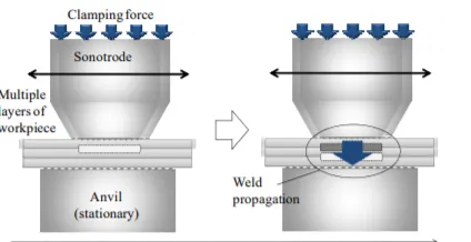
Ultrasonic metal welding is a process in which a high frequency, usually 20 kHz or above, of ultrasonic energy is used to produce oscillating shears to create solid-state bonds between two sheets clamped under pressure. The main advantage of ultrasonic welding is that it works well for dissimilar materials and multiple sheets (Figure 4), which is crucial for cell joining as well as for battery tab joining [24]. Ultrasonic welding is attractive for battery manufacturing because of its low temperature and relatively good performance for Al, Cu and other highly conductive materials. In addition, ultrasonic metal welding is also environment-friendly since it does not use any filler metals or gases.
Mechanical joining:
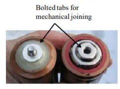
Mechanical joining can be categorized by two distinct groups: fasteners and integral joints. Fasteners include nuts, bolts, screws, pins and rivets. Integral joints include seams, crimps, snap-fits, and shrink-fits that are designed into the components to be connected.
In the battery pack manufacturing, welding can be an effective solution on a small scale joining, e.g., for connecting multiple battery cells through battery tabs or bus bars,. However, when applied to module-to-module joining, welding may be not appropriate for joining those large modules due to battery maintenance and service concerns. Instead, by using threaded bus bars or metal rods, individual units or modules
can be fastened by bolts and nuts. Hence, the major advantage of mechanical joining is the ease of disassembly for maintenance and repair. In addition, mechanical joining is generally performed without heating except maybe in a few particular cases (i.e. interference fit ).
- Different type of materials used for makng these connections are shown below,