Week - 4
Objective:
- Implement control logic of a “washing machine” using Stateflow.
- Make a Simulink chart for the “Gear shift” logic.
Introduction:
- Implement control logic of a “washing machine” using Stateflow.
Conditions to be followed while simulating the following model are,
- If the power supply is available, the system gets activated
- If the Water supply is not available, stop the process & indicate through LED
- Soaking time should be 200s followed by Washing time of 100s.
- Then rinsing happens for next 20s & dryer runs for 50s.
- After all the processes have completed turn on the finished LED.
Procedure:
- Open matlab and go to simulink.
- In the blank sheet first open Chart. To define the state flow we enter the chart and select a state.
- First state is named as Power supply. Input needs to be given to the power supply. In this case we represent y=1 as the On condition. Now if the power supply is in ON condition then only water supply needs to be given. If the power supply is OFF (y=0), water supply won't take place.
- To give water supply we define one more state named as Water. ON condition of water supply is represented by X=1. If the water supply is OFF (X=0), Led needs to be blinked red. Therefore we take one more state and name it as Water_LED.
- After the water supply ON condition, we first need to soak the clothes, therefore we take a state named as Soaking. Now soaking is gonna take place for 200 sec, therefore after(200,sec) condition is given.
- After soaking we need to wash the clothes, therefore we introduce one more state named as washing. Washing needs to take place for 100 sec, therefore after(100,sec) condition is defined before moving on to the next state.
- After washing, we need to rinse and dry the clothes, therefore two more states are defined named as Rinsing and Dryer. There respective time delay is defined accordingly.
- At last we need to show the process is done through a LED, therefore we define last state as LED.
- Now for all the states, display=1 means that the respective state is in working condition.
- To define the input we can take a constant. Constant value of 1 means ON condition and 0 means OFF condition.
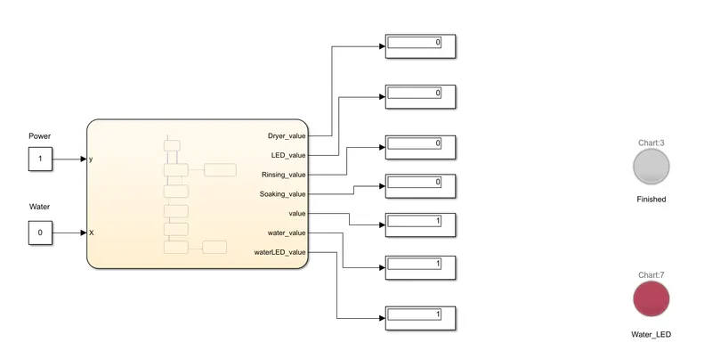
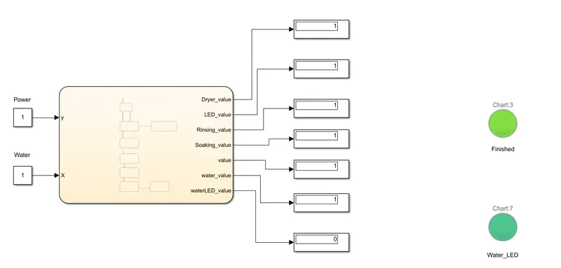
- To indicate the response through LED, we can take Lamp. Red colour of the lamp indicates state value 0 and Green colour indicates state value 1.
Results:
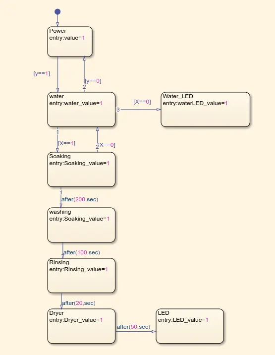
Figure-1 Chart
- Case-1: When the power supply is ON and water supply is OFF.
- Case-2: When the power supply is ON and water supply is ON.
2. Make a Simulink chart for the “Gear shift” logic.
Conditions to be followed while simulating the following model are,
Speed Range(kmph) Gear
0 to 15 1
16 to 25 2
26 to 40 3
41 to 60 4
Above 61 5
Give speed input while the simulation is running & display the gear number.
Procedure:
- Open matlab and go to simulink.
- In the blank sheet first open Chart. To define the state flow we enter the chart and select a state.
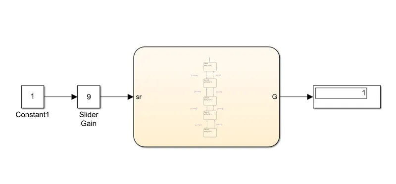
- First state is name as Gear. Direct input is given to Gear. If the input speed range is between 0-15 kmph, display value is 1, which represents gear-1. Input is represented by sr and if the condition is sr>=16, signal goes to the next state.
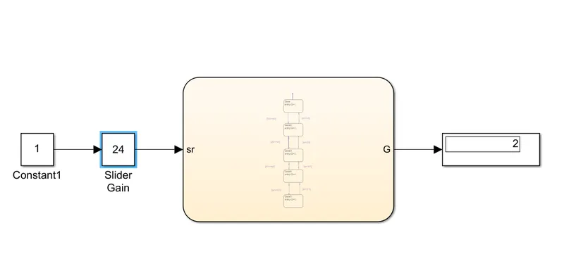
- For a speed range of 16-25, state Gear2 is defined. If the condition is sr>=26, signal goes to the next state otherwise display vaue shows 2, which represent gear-2.
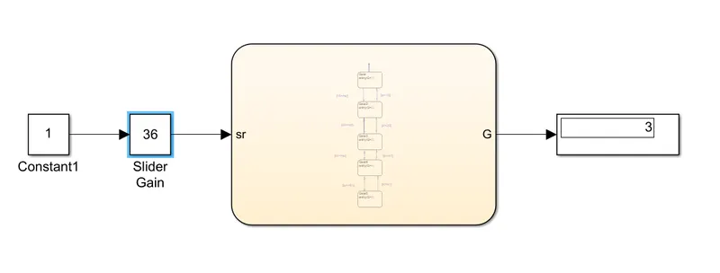
- Gear 3 operates between 26 to 40 kmph, therefore state 3 is defined and named as Gear3. If the condition is sr>=41, signal goes to the next state otherwise display vaue shows 3, which represent gear-3.
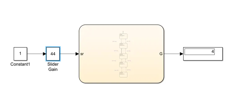
- Gear 4 operates between 41 to 60 kmph, therefore state 4 is defined and named as Gear4. If the condition is sr>=61, signal goes to the next state otherwise display vaue shows 4, which represent gear-4.
- Gear 5 operates for speed more than 61 kmph, therefore state 5 is defined and named as Gear5.
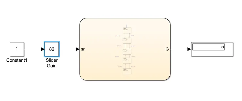
- Input can be given as a constant value or using a slider gain block. I used Slider gain block. Maximum and minimum limits of the slider are ste between 0 and 100 and a gain of 1 is given.
Results:
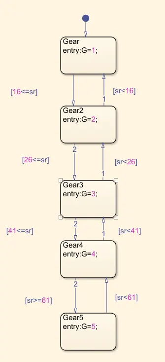
Figure-2 Chart
- Case-1: Slider is moved to 9kmph and the display is gear-1
- Case-2: Slider is moved to 24kmph and the display is gear-2
- Case-3: Slider is moved to 36kmph and the display is gear-3
- Case-4: Slider is moved to 44kmph and the display is gear-4
- Case-5: Slider is moved to 82kmph and the display is gear-5
Conclusion:
- Both model works as per the given conditions.