Project 1 Mechanical design of battery pack
Project 1 Mechanical design of battery pack
Battery pack capacity: 18 kWh
Cell: ANR26650M1-B
We have to design the battery pack for the same :
So to begin this process , I have structured the entire process in the specified steps so that it is easy for you to understand the mechanism and the calculations involved throughout .
LETS BEGIN :
1) Selecting the cell for the performance of the battery . Here it is already given the cell so no need to select here .
CELL NAME : ANR26650M1-B
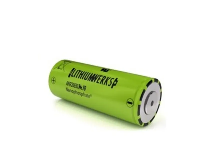
CELL SPEC DATASHEET :
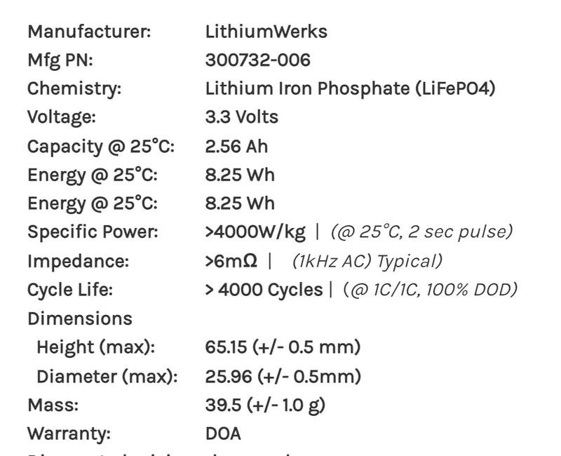
So from the sheet , we can clearly see that
VOLT = 3.3 V
CURRENT CAPACITY = 2.56 AH
2 ) Converting the battery capacity from KWH to AH so that it is easy for us to calculate in same units .
FIRST ASSUMPTION : We assume that Voltage of battery is 400 V . This is due to the fact that the ideal Motors run at 400V to achieve their MAX power and torque .
V = 400 V
We know , battery capacity = 18 KWH , V = 400 V
Then , current capacity is POWER / VOLTAGE
I = 18000 / 400 = 45 AH
- This means that the Current which will be provided by the entire battery pack with all cells arranged ion series and parellel combo will be 45 A .
- This also means that the battery will take complete 1 hour to get discharged if the discharge rate has been equal to the 1C rate .
SO I = 45 AH
3) Calculation of No of cells required to achieve 400V , 45 AH
We know ,
for 1 cell , V= 3.3 V , I = 2.56 .
So we know that , SERIES COMBO = VOLTAGE ADDITION
PARELLEL COMBO = CURRENT ADDITION
For No of series cells = total voltage / per cell volatge
400 / 3.3 = 121.21 = 122 ( for safe side )
SERIES CELLS = 122
For No of parellel cells = total current / per cell current
45 / 2.56 = 17. 57 = 18 ( for safe side )
PARELLEL CELLS = 18
So the required no of cells are = series cell x parellel cells
122 x 18 = 2196
TOTAL CELLS = 2196
- So this means that the battery will be configured as 122S18P to generate a power of 18.117 KWH for a motor which is running at 400 V with the group of 2196 cells .
4) Pack dimensions and mechanical structure .
ASSUMPTION : For better allignment and less complexity of pack while installation , I have divided the entire series and parellel combo into 2 smaller packs .
ASSUMPTION : The clearance between 2 cells is 3 mm .
ASSUMPTION : The height of joining structure above cell is 30 mm .
SO NET POWER BY BATTERY PACK = 2 x POWER BY SMALLER SUB PACKS
Now length of 1 pack = (DIA of 1 cell + clearance between the cell( kept for thermal management)) x no of cells
(26 + 3 ) x 61 = 1769 mm = 1.769 m
Now width of 1 pack = (DIA of 1 cell + clearance between the cell( kept for thermal management)) x no of cells
(26 + 3 ) x 9 = 261 mm = 0.261 m
Now hieght of 1 pack = hieght of cell + height of joining structure
65.2 + 30 = 95.2 mm = 0.0952 m
So volume occupied by the battery pack = L X B X H
Volume = 1.769 x 0.261 x 0.0952
V = 0.043 m^3
So for 2 packs = 0.043 x 2 = 0.086 m^3
SO NET VOLUME OCCUPIED BY BATTERY PACK = 0.086 M^3
5 ) Joining of cells and also the allignment of 2 packs to assemble the entire the battery pack .
Now in order to make the mechanical connection betwwen the cells , I have applied a welding technique
- RESISTANCE SPOT WELDING
The reason that why I have chosen this technique is that
- It is easy to weld in complex areas
- It is the oldest successful technique
- Current is used for welding purpose so no use of fire to weld .
- Has very good strength at the joint so that the copper aluminuim chip could not run away .
- Also it is very famous in case Li ion cell joints .
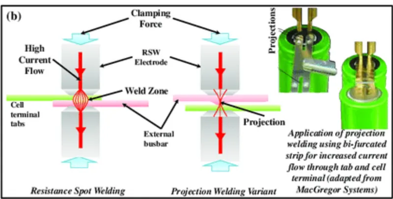
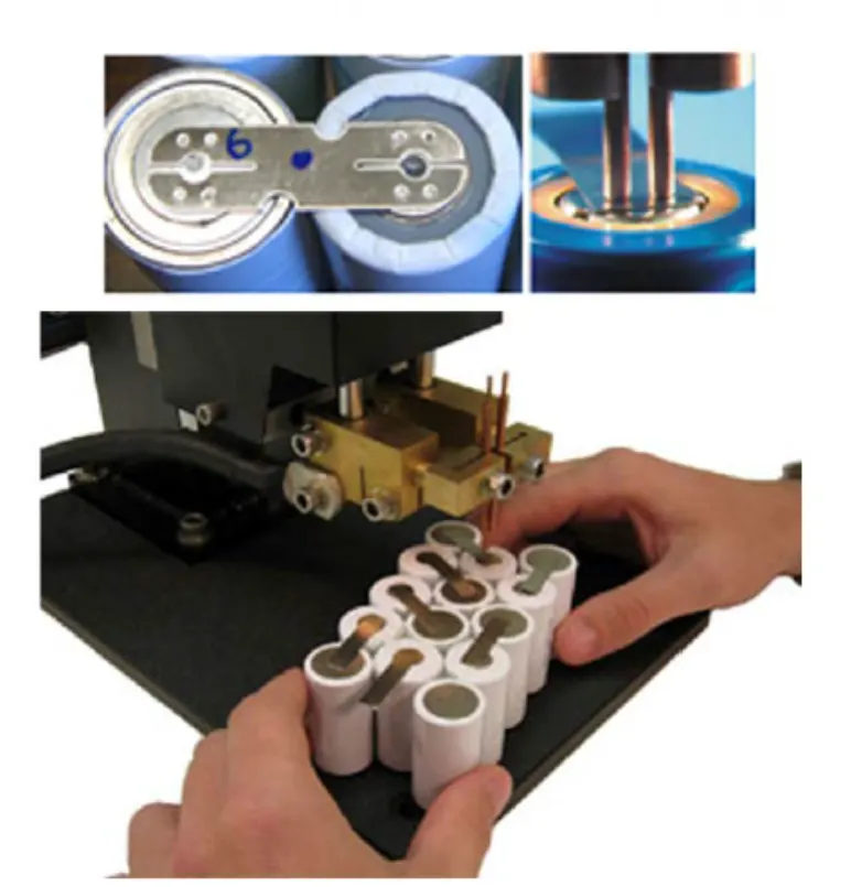
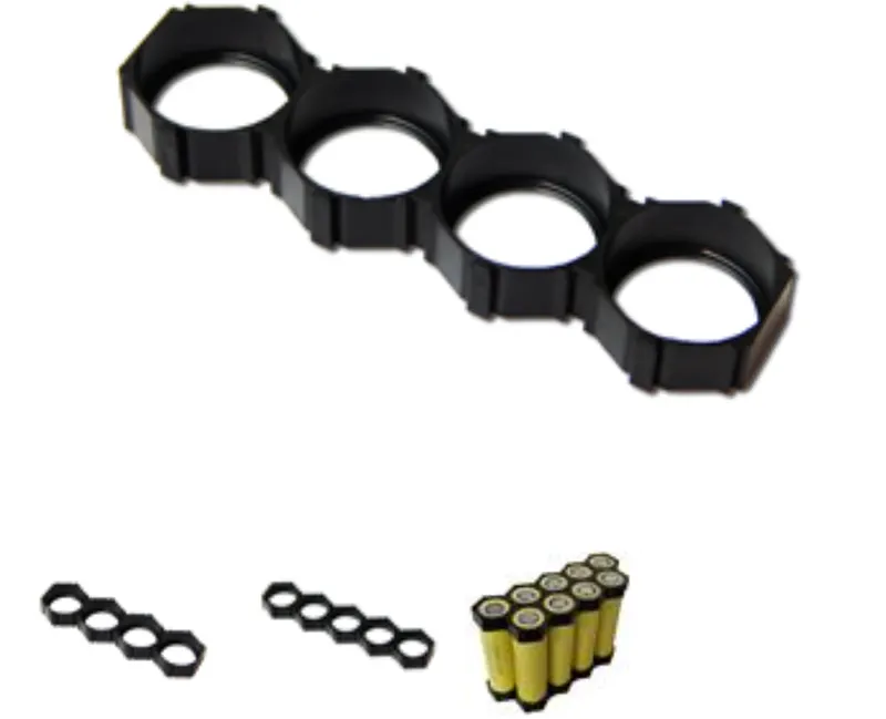
- Now these cells are placed in cell holders for proper balance and also to absorb the shock comming from external envirnoment . These cells are placed in these holder in both combinations as required .
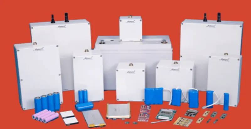
- After it they are assembled in the mechnical outer body , also known as THE BATTERY CASE in which they kept along with the thermal management unit and finally the entire battery pack is assembled .
So these are the following steps that are responsible for proper structured mechanical desgn of the battery .