Project 1 Mechanical design of battery pack
AIM: Design of Battery Pack with following Given Specification:
- Battery pack capacity: 18 kWh
- Cell: ANR26650M1-B
Design Overview & Procedure: A battery pack is a system of multiple components and functions and its design involves the application of knowledge and practice in the electrochemical, electrical, mechanical, thermodynamic, and control fields. The following sections summarize the various stages of a battery pack design, covering specific aspects of the A123 cells which may be unique from other cells.
- First determine the configuration of cells, i.e. how many cells overall, how many are in series, and how many are in parallel. This is the foundation of the design process, since all other design decisions follow from the cell configuration.
- Design a mechanical structure around the cells to support and protect them. Here we requires knowledge of electrical, mechanical and thermodynamic and properties of the cells, application, and the materials used in the pack.
- Use suitable Interconnection method and pack it tightly.
- Design the protection of the cells, particularly electrical protection. The pack must be protected from inadvertent short circuits internal and external to the pack as well as excessive charging and discharging imposed on its terminals.
- Design a control system that monitors and manages the cells, keeping them from being damaged and maintaining the pack at peak performance.
- Finally, a pack performs best when it is used properly. The final section of this chapter describes how to charge and discharge the battery pack to make it perform its best.
Decoding Naming Convation: ANR26650M1-B
ANR26650M1-B rechargeable battery (or accumulator) has a
Technical characteristics:
| Nominal Voltage | 3.3 V |
| Fully charged voltage | 4.6 V |
| Cell Weight | 76 Gm |
| Operating Temperature | -30°C to 55°C |
| Cell Capacity (nominal/minimum) (0.5C Rate) | 2.5/2.4 Ah |
| Nominal discharge current | 2.5 A |
| Dimensions | Ø26 x 65mm |
| Capacity of single cell = Cell Voltage* Ah rating | 3.3*2.5 = 8.25 WH |
| Internal resistance | 10 mΩ |
| Capacity at nominal voltage | 2.3 |
| Exponential zone | [4V, 0.4Ah] |
Performance Analysis of Cell: Analysis of Charging and Discharging of Cell at different temperature and C-ratings. And its cycle life.
Voltage Requirement:
- Voltage levels of 400 to 800 V or more are needed to generate sufficient power to run the vehicle.
- Each cell voltage is 3.3V and pack voltage should be 429 Volt, therefore 130 cells are needed to be connected in series.
N s = 330 3.3 = 100 N s = 330 3.3 = 100
Capacity Requirement:
- Required capacity is 18000wh.
- As voltage is assumed to be 429 V, Therefore current output at terminals of battery pack is
18000 429 = 41.95 A h ≈ 42 A h 18000 429 = 41.95 A h ≈ 42 A h - Single parallel path produces 2.5Ah, therefore
41.95 2.5 = 21.3 = 16.78 ≈ 17 41.95 2.5 = 21.3 = 16.78 ≈ 17
Total Number of cells:
- Number of cells in series multiplied by number of cells in parallel=130*17=2210 cells are required.
Mechanical design of battery pack:
Cell: cell is used to store chemical energy at the time of charging and at the time of discharging it delivers electrical energy. Cell consist of anode ,cathode and lithium iron phosphate (LiFePO4) material.
Dimension:
- Length of cell is 66mm.
- Diameter of cell is 26mm.
Module: To increase cell ratings, same types of cells are connected in series and parallel.
- Extra 2 mm length is taken for cell strips and distance between cells assume to be 4mm.
- Assuming 26 cells are connected in series in module.Therefore rating of cell is Voltage =26*3.3=85.8V
- Ampere hour remains constant as cells are connected in series.
- Total modules =2210/26= 85.
- If we connect 5 modules in series , It deliver 429V and 2.35Ah and here it form one parallel path.
- Each parallel path consist of 5 modules and these should be repeated for remaining 17 parallel paths.
- This is one of the module configuration. Other module configurations are also possible.
- Thus the battery model is said to be 130S17P configuration (130 series and 17 parallel connections), which gives us (130*17 =2110 cells). From this we have created overall capacity of battery pack as (429*42Ah=18018Wh) which is slightly higher than 18 KWh.
- The overall Capacity(Ah) of battery pack is given as 2.5Ah * 17 = 42Ah.
- Which means it provided 42 A of current continuously for one hour to full discharge.
- Thus 17 modules should be arranged in a way as battery pack to fit in an EV chassis.
Using Cylindrical cell : Cylindrical cells are the most common cell type in use today. This design allows for better automation processes and techniques that increase consistency and lower cost.
Compared to prismatic cells, cylindrical cells can be produced much faster so more KWh per cell can be produced every day equaling lower $ per KWh. The electrodes in a cylindrical cell are wound tightly and encased in a metal casing, This minimizes electrode material from breaking up from the mechanical vibrations, thermal cycling from charging and discharging and mechanical expansion of the current conductors inside from thermal cycling. Many cells are combined in series and in parallel to increase voltage and capacity of the battery pack. If one cell goes bad, the impact on the entire pack is low. With prismatic cells if one cell goes bad it can compromise the whole battery pack. Cylindrical cells radiate heat and control temperature more easily than prismatic cells.
Methods of Connection of cells:
Series Strings: Cells combined in series strings can achieve higher operating voltages by connecting the positive terminal of one cell to the negative terminal of the next cell. Connect strings of series cells using their current collection tabs in a manner similar to that illustrated in Figure.
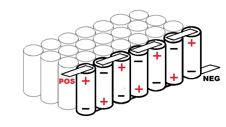
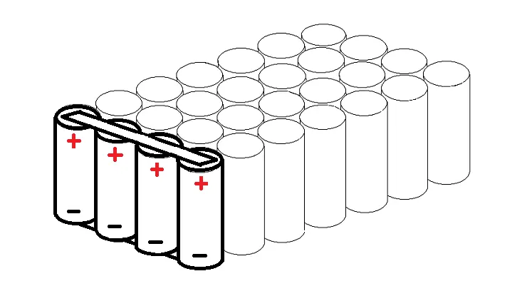
Parallel Strings: Cells combined in parallel strings can achieve higher operating capacities by connecting like-polarity terminals of adjacent cells to each other. Connect strings of parallel cells using their current collection tabs in a manner similar to that illustrated in Figure .
The Gap Between Each Cell : The cell vents, located on the end cap(s) of the cells (on the POSITIVE side of the cell), should not be blocked by any mechanical means. Blocking the cell vent and then sufficiently abusing the cell so as to build up pressure in the cell prevents the cell from properly venting. An ESS designed to install cells end-to-end needs at least 1 mm of space between the cells to allow the vent to open under fault conditions.
Cell Interconnects : Size cell interconnects for the expected maximum current carrying capability. Improperly connection can cause heat up excessively, resulting in even higher resistivity.
- Battery pack constructions consist of three major levels of processing namely cell level, module level, pack level constructions.
- The electrodes are combined with electrolyte to various cell models as cylindrical, prismatic, pouch type cells.
- After case sealing cells are combined to form module level construction. Finally these modules are combined to form pack level constructions.
The interconnections between cells/modules are practised by various welding techniques. Some of them are:
- Ultrasonic metal welding.
- Resistance welding.
- Laser beam welding.
- Wire bonding.
- Mechanical Joining.
- Adhesive bonding.
- soldering and brazing.
Ultrasonic metal welding: Ultrasonic metal welding or UMW, is a solid-state welding technique which forms a bond by applying moderate static pressure and an ultrasonic oscillation of about 20 kHz between two parts of metal. The solid-state weld is formed through the high frequency motion between the parts causing continuous shearing and plastic deformation, while also removing any oxide layers or contaminants.
Most metals can be ultrasonically welded and the method is excellent for welding together thin foils, as well as thicker sheets with spot or seam welds and also wires.
The four types of materials welded in this process can be seen as, Ultrasonic seam welding, Copper and aluminium welding, Aluminium wire welding on copper & Multilayered copper foil welding.
Resistance spot welding: One of the oldest welding methods is resistance spot welding (RSW). RSW is a technique where two or more metal sheets are welded together through the application of an electrical current and pressure between two electrodes. The electrical resistance of the material at the interface results in the generation of heat and melts the materials together without the use of filler material or gases.
The temperature increases in the affected area, the interface, and eventually reaches the material’s melting point. A weld nugget forms in the affected area after cooling. This is a small volume of the material which has melted and then fused together.
Laser beam welding: Laser beam welding (LBW) is a welding technique in which a laser beam provides a concentrated heat source that fuses the materials together. LBW is commonly performed using keyhole mode welding in which the extreme power density of the laser beam causes the metal to melt and evaporate.
As the metal atoms evaporate from the surface, forces in the opposite direction of the evaporation causes a local vapor pressure. The vapor pressure creates a hole which is known as the key hole by depressing the molten metal. below method and the welding of busbars to cylindrical battry cans also shown.
Wire bonding: Wire bonding, schematically depicted in Fig. below, is a frequently employed joining technology in semiconductor device technology. Here, a wire is joined onto an integrated circuit board in order to create connections. Those connections are most commonly manufactured by means of thermo-compression bonding, ultrasonic (wedge) bonding, and thermo-sonic bonding. The joints are recommended to be made by ultrasonic wedge bonding, but any other process may be used. The wires shall be of aluminium and have a diameter of 0.28 - 0.41 (mm). The collector plate shall be of any electrically conducting material, preferably metal.
Enclosures: A battery enclosure is a box designed to protect batteries from potential weather and battery mishaps. They can be designed for indoor or outdoor use, and may include room for electronics. Specific designs allow for pole, wall, or ground mounted systems.
The NEMA rating on the other hand is commonly used in North America. It considers the IP rating as well as other specifiers such as corrosion and construction details. The scale ranges from 1-13 with 7-10 being designed for Hazardous Locations and 1-6, 11-13 designed for Non-Hazardous Locations.
These are the types of NEMA enclosure ratings, and their various forms of protection in outdoor non-hazardous locations. All SunWize enclosures are designed to NEMA3R, which provides a high degree of protection from the elements in rugged and exposed outdoor locations.
- Lego connector: Here we using the lego connector Because In this easy to connected the cells, when the the one cell is fail, easy to deconstruct. same way the best electrical and mechanical connection. Lego Connection are best suitable for Cylindrical cells, which are the most common cell type in use today.
- Nickel Strip: Conductive metal strips are spot welded between all the cells of an electric bicycle battery pack. Nickel is the material of choice due to its low relative resistance and ease of spot welding. Steel is cheaper than nickel, which is why many vendors sell nickel coated steel strips. It brings the cost down, but at the expense of pack health. Because steel has higher resistance, the same size strips will heat up more, wasting energy from your pack. This not only cuts down on your range but also damages your battery by cooking it slowly over time with extra heat.
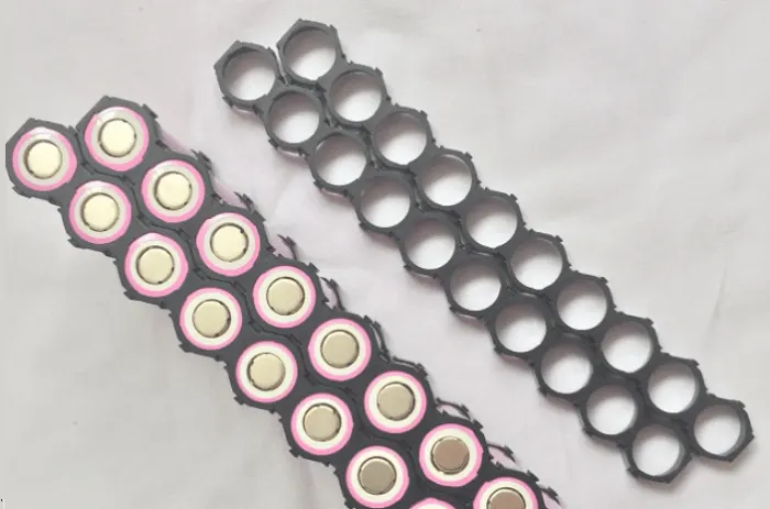
- Cell holders: These holders are used for holding the individual cells in a better posture without mis-assemble.The connections can be made accordingly to make series connections and parallel connections to form the required module dimensions. After installind the cells in a individual module the entire maximum positive terminal and maximum negative terninal are made under single pair of erminals as shown below.
Battery Cabinet arrangements: Each modules are interconnected in series or parllel according to the requirement and packed as a single large cabinet pack as shown below.
Battery pack arrangement: Finally the overall battery pack after the arrangement of all cabinet connections with enclosure looks like this as shown below,
Matlab Model of battery Pack:
- Here, 130S17P batteries are used with one module of 26 Cells.
- One Sub-system having 26 numbers of indivisual cells.
- There are 5 such sub-system connected in series, to make total voltage of 429V.
- There is 17 such parallel path comprising (26*5) series.
- This whole combining makes 429V with 42Ah with rating of 18KW.
Block Used:
- Voltage Sensor.
- Current Sensor.
- Scope.
- battery.
- Bus Selector.
- Powergui.
- signal guilder block.
Referances:
- https://lithiumwerks.com/products/technology/chemistry/
- https://datasheetspdf.com/pdf/1424845/A123Systems/ANR26650M1-B/1
- https://www.audiophonics.fr/en/battery-and-accumulators/a123-systems-rechargeable-battery-lifepo4-26650-33v-2500mah-unit-p-14038.html
- https://www.sciencedirect.com/science/article/pii/S2666330920300157