Project 1 - Loss calculation for a DC/DC converter-MATLAB
- Extending the learned lessons in previous module, you will be diving into another power electronics concept on your own.
- Design of boost converter, and calculating the loss of different components including power switching device and deriving efficiency of boost converter. This is applicable in power supply industry, electric vehicles etc where DC-DC converter is required to boost the voltage from DC source. All the aspects of this project with loss calculation, device selection, simulation etc are industry relevant.
Answer:
Aim: Design and simulate the boost converter. Calculate the losses and efficiency of the boost converter.
Theory:
Boost converter:
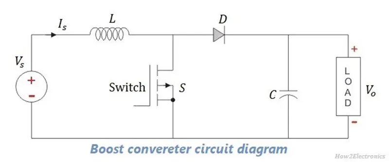
The boost converter is a DC-to-DC converter designed to perform the step-up conversion of applied DC input. In the Boost converter, the supplied fixed DC input is boosted (or increased) to adjustable DC output voltage i.e. output voltage of the boost converter is always greater than the input voltage. So, a Boost converter is also called a step-up converter or step-up chopper.
The figure given below is the circuit representation of the boost converter:
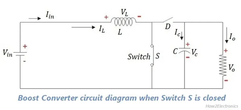
Mode I: Switch S is ON and Diode D is OFF
In this mode of operation, switch S is in closed condition i.e. ON state, and diode D is in open condition i.e. OFF state. Thus switch S allows the flow of current through it. All the current will flow through the closed path including inductor L, switch S, and back to the dc input source. The circuit diagram for this mode is shown in the figure below.
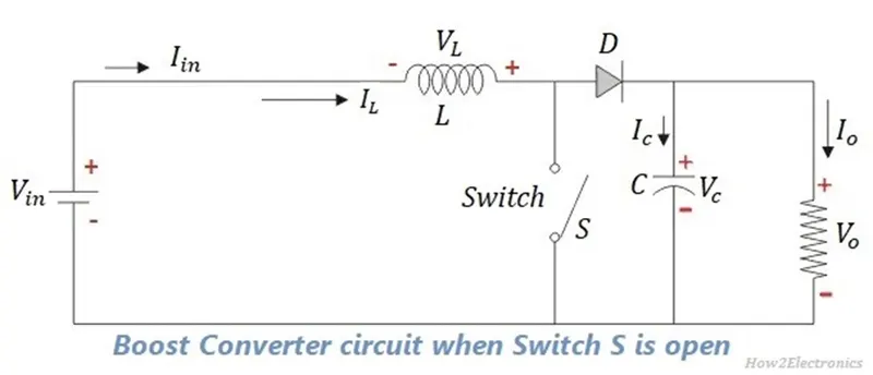
Mode II: Switch S is OFF and Diode D is ON
In this mode of operation, switch S is in open condition i.e. OFF state and diode D is in closed condition i.e. ON state. Thus switch diode D allows the flow of current through it, whereas switching S blocks the current flow through it. The circuit diagram for this mode is shown in the figure below.
Design Parameters are listed below:
Vin = 100V
Vout = 200V
Fsw = 20kHZ
L = 200uF
C = 400uF
R = 10 ohms
rL = 10 m ohms
rC = 2 m ohms
rd= 5 m ohm
Duty Cycle:
Vout/Vin = 1/(1-D)
200/100 = 1 / (1-D)
2 = 1 / (1-D)
2*(1-D) = 1
(1-D) = ½
(1-D) = 0.5
D = 1-0.5
D = 0.5
The boost converter simulation model is shown below:
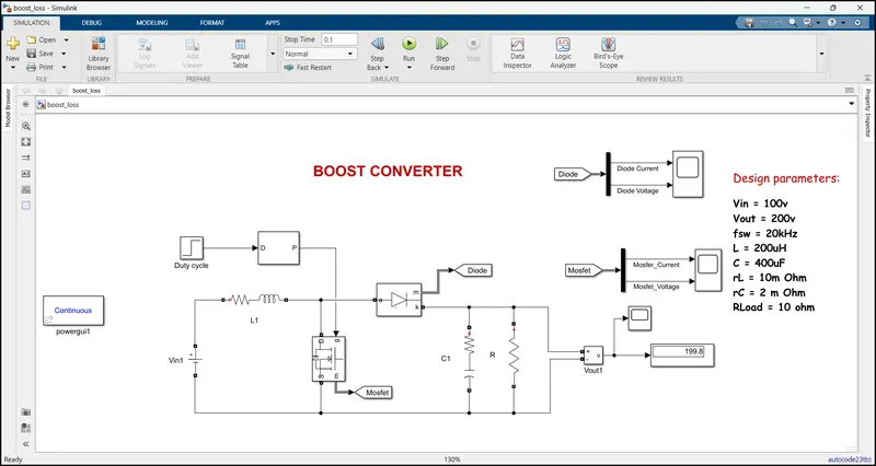
Model explanation:
To model the boost converter, a dc voltage source is taken as input supply with 100v. and a series RL(Inductor(L) and parasitic inductance resistance rL) branch is connected in series with input supply.
For switching operations, a MOSFET is connected parallel to the inductor and diode connected in series. The capacitor and Resistive loads are connected in parallel to the diode.
MOSFET and DIODE blocks measurement ports are connected to goto tags. These tags are connected to a demux block to separate the signals and connected to scope individually.
A voltage measurement block is connected across the Load resistor to observe the output voltage and it was given to display block and scope.
Each block’s properties are shown below:
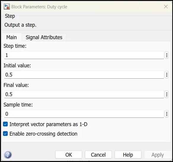
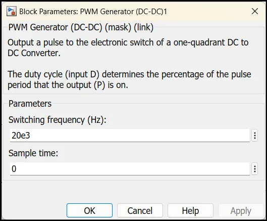
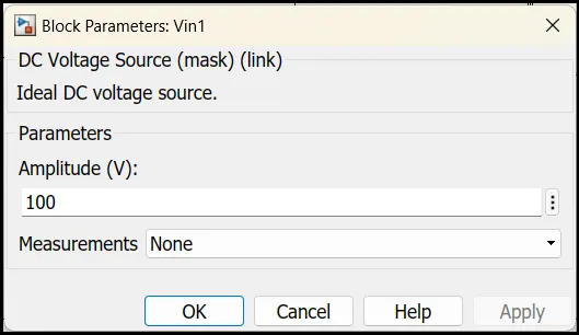
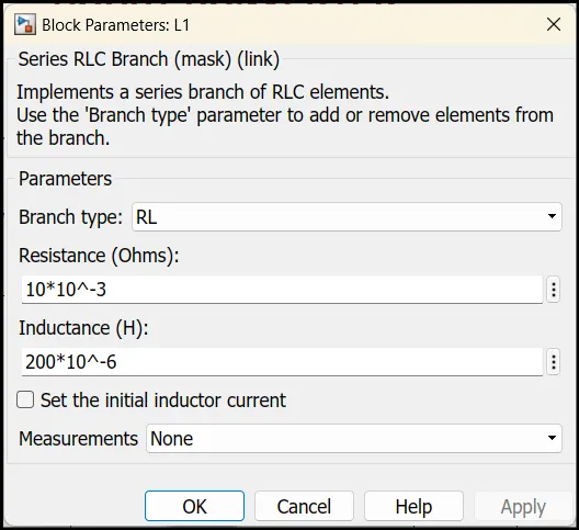
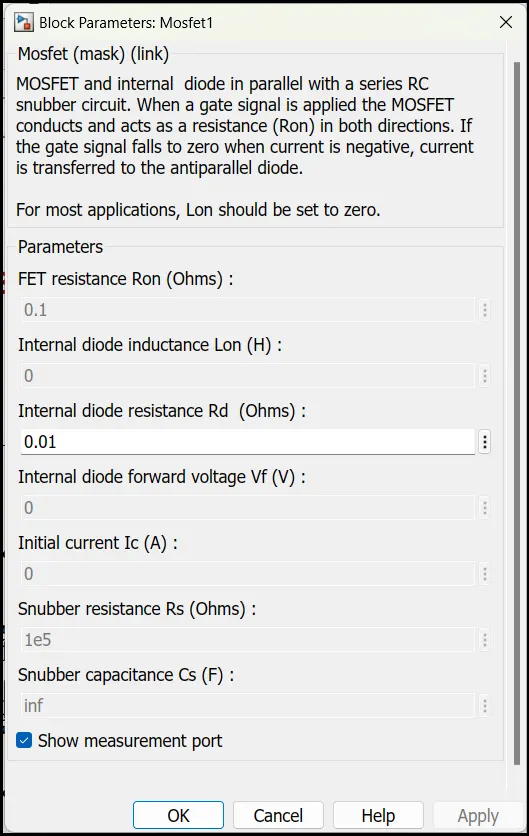
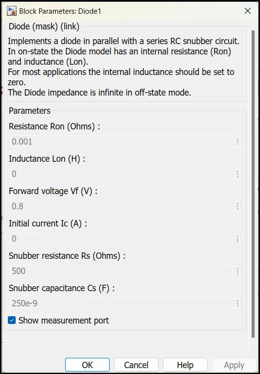
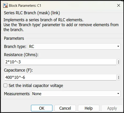
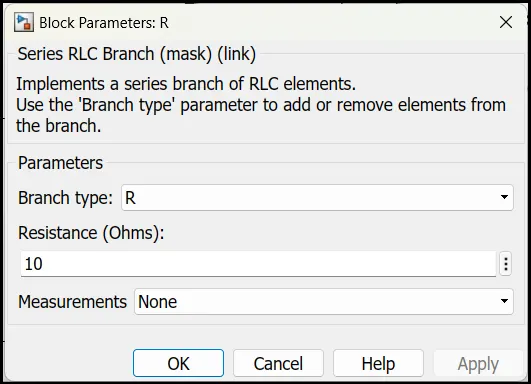
Result:
Output voltage:
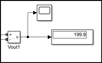
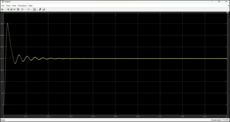
From the above plot, we can observe the output voltage of the boost converter is reached to 200V.
the input 100V is step up to 200v by using the boost converter.
Mosfet Voltage and Current:
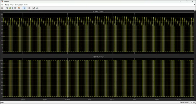
From the above plot, top plot is mosfet current and bottom plot is mosfet voltage.
Diode Voltage and Current:
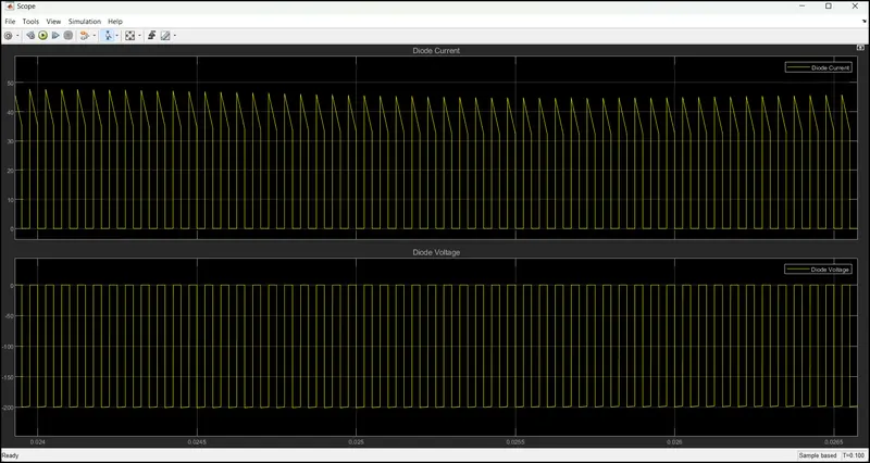
The Loss Calculation of boost converter:
The Boost converter has four types of losses. They are:
- Conduction losses
- Diode losses
- Induction losses
- Capacitor losses
Conduction Losses:
Conduction Losses: Pc= I² * Rds *D
p= Power Dissipation
I= Current through MOSFET
R= Resistance in Ohm
D=Duty Cycle
Im = Pi/Vi = (V^2/R)/Vi
= ((100)^2/10) / 100
Im =10
Pc= 10^2 * 0.023 * 0.5
Conduction loss Pc = 1.15w
Diode losses:
Diode Losses: P= Vf * I* (1-D)
Vf= forward voltage
I= Current output
D=Duty Cycle= Vout / Vin
P = 19.55 * 1 * (1-0.5)
= 9.775
Diode losses P = 9.7 W
Induction Losses:
Pd= I² * R + { (rl / 12) (D* Vin / F*L)}
I= Current output
D=Duty Cycle= Vout / Vi
F= Frequency
L= Inductance value
Pd = 1^2 * 10 +{(0.0008 * 5000}
Inductor loss Pl = 10W
Capacitance losses:
Pc= {rc* D*(1-D) I² + {rc / 12(1-D)}}*{(Din / C*F)}
I= Current output
D=Duty Cycle= Vout / Vi
F= Frequency
C= Capacitance value
Pc = 2*0.5*0.5 + {(2*0.0001*0.5*0.5*100) / (400*50*1*10^-6)}
Pc = 0.7085W
Total Losses= Pcon+Pd+Pi+Pc
=5+9.775+1.4+0.7085
Total losses=11.74585 W
Efficiency Of Converter:
The Efficiency Of converter is determined by using below formula:
Efficiency = (Pin -Ploss / Pin ) 100
From the data
Pin= Vin * I
I= Vin / R
=100 / 10
I= 10 Amps
Pin = vin * I
=100 * 10
Pin=1000 W
Efficiency = (Pin -Ploss / Pin )100
= 1000-11.74 / 1000 100
Efficiency = 98 %