Project 1 - Loss calculation for a DC/DC converter-MATLAB
- Extending the learned lessons in previous module, you will be diving into another power electronics concept on your own.
- Design of boost converter, and calculating the loss of different components including power switching device and deriving efficiency of boost converter. This is applicable in power supply industry, electric vehicles etc where DC-DC converter is required to boost the voltage from DC source. All the aspects of this project with loss calculation, device selection, simulation etc are industry relevant.
DC voltage source:-
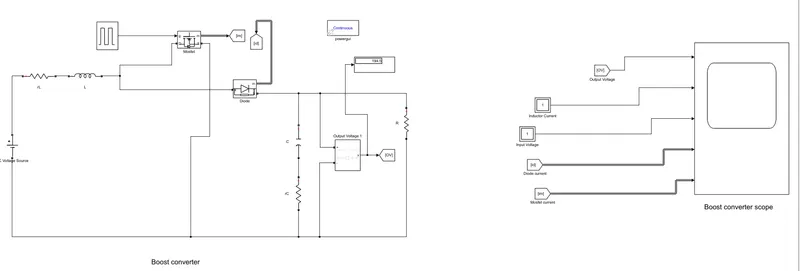
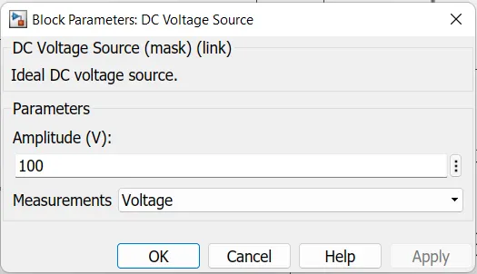
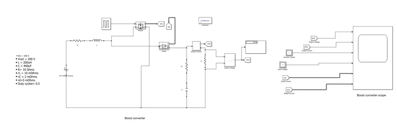
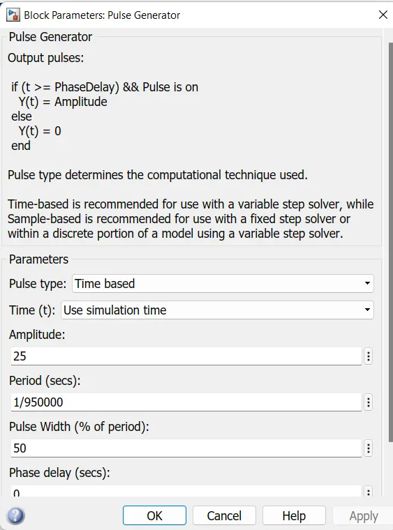
Pulse generator parameter
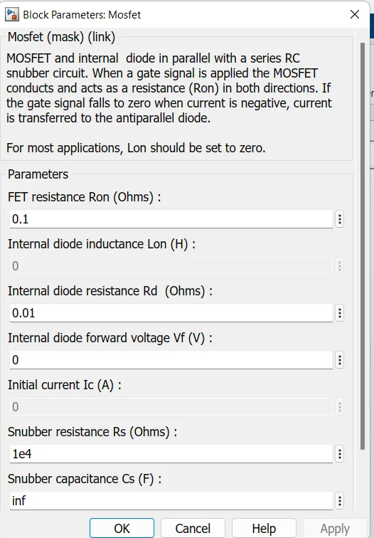
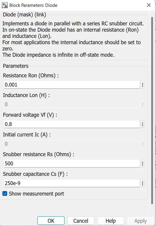
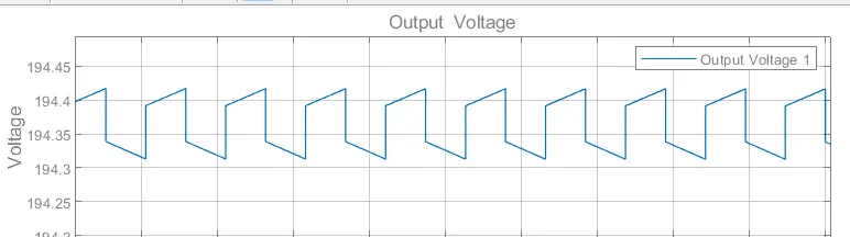
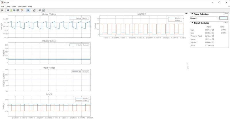
Result: From the above graph, we can see the Output voltage is greater than the Input voltage. The input voltage of 100v is boosted to 194 voltage.
The result can be verified from the scope as well as the display box.
In any DC-DC converter majorly consider 4 types of losses are as followes:-
- Conduction Losses
- Diode losses
- Induction Losses
- Capacitor Losses
Conduction Losses:-
Conduction losses are a result of device parasitic resistances impeding the DC current flow in a DC/DC converter. These losses are in direct relationship with the duty cycle.
When the integrated high-side MOSFET turns on, the load current flows through it. The drain-to-source channel resistance (RDSON) causes power dissipation.
Formula :-
Conduction Losses:- Pc= I^2 * D ------(1)
were,
p= power dissipation
I= current through MOSFET
R= Resistance in OHM
D= duty cycle = Vout/ Vin
Diode losses:-
The diode is forward-biased when the integrated MOSFET turns off. During this time, the inductor current ramps down through the output capacitors, the load and the forward-biased diode. Since the load current is now conducting through the diode, there will be power dissipation in Diode.
This will be calculated by using below Formula:-
Diode Losses:- P= Vf * I* (1-D) -------(2)
were,
Vf = forward voltage
I= output current
D= duty cycle = Vout/ Vin
Induction Losses:-
The conduction losses depend on the load current. With heavier loads, the conduction loss in the MOSFET increases and is the dominating factor. Conduction losses plus switching, driver and internal low-dropout regulator (LDO) losses lead to a considerable generation of heat.
This losses can be calculated by using the below formula:
Pd= I^2 *R + {(rL/12) (D* Vin/ F*L)} ------(3)
were
I= output current
D= duty cycle = Vout/ Vin
F= frequeny
L =inductance
Capacitence losses:-
While getting the output throught the capacitor we can get some power dissipation in capacitor also.
this power dissipation is determined by using the following Formula:-
Pc = {rC* D * (1-D) *I^2 + (rC/ 12 (1-D)) * {(Din / C*F)} ------(4)
were
I= output current
D= duty cycle = Vout/ Vin
F= frequeny
C= capacitance
From the given data we can find the losses for Designed DC-DC Converter:-
- Vin = 100 V
- Vout = 200 V
- L = 200uH
- C = 400uF
- R= 10 Ohms
- rL = 10 mOhms
- rC = 2 mOhms
- rd=5 mOhms
- Duty cyclee= 0.5
Conduction Losses:-
from the equatation (1)
Conduction Losses:- Pc= I² * R *D
Pc= (1)² * 10*0.5
Conduction Losses (Pc)=5W
Diode losses:-
From the equatation (2)
Diode Losses:- Pd= Vf * I* (1-D)
= 19.55 * 1 * (1-0.5)
= 19.55*0.5
Diode Losses(Pd) =9.75 w
Inductior Losses:-
From the equatation (3)
PI= I² * R + { (rl / 12) (D* Vin / F*L)}
=1² * 10 +(0.0008*5000)
= 10+4
PI =14 W
Capacitance Losses:-
From the equatation (4)
Pc= {rc* D*(1-D) I² + {rc / 12(1-D)}}*{(Din / C*F)}
=2*0.5*0.5+(2*0.0001*0.5*0.5*100 / 400*50*0.000001)
Pc= 0.7085 W
Total Losses= Pcon+Pd+Pi+Pc
=5+9.775+1.4+0.7085
Total losses=11.74585 W
Efficiency Of Converter:-
The efficiency Of converter is determined by using below formula:
Formula:-
Efficiency = (Pin - Ploss / Pin) * 100 --------- (5)
From the data
Pin= Vin * I
I= Vin / R
=100 / 10
I= 10 Amps
Therefore,
Pin = vin * I
=100 * 10
Pin=1000 W
From above equatation(5)
Efficiency = (Pin -Ploss / Pin )100
= 1000-11.75 / 1000 100
Efficiency = 98.825 %
Results :-
The total Power losses Ploss= 11.75 W
The efficiency of Converter = 98.825 %