Week-6 Challenge: EV Drivetrain
1. Which types of power converter circuits are employed in electric and hybrid electric vehicle?
The Electrical vehical are classified as below:
Battery Electrical Vehical, Hybrid Electrical vehical, Fuel Cell Vehical.
The main component of the electrical vehical is the power converter which is used in the vehical are mentionn below.
1. DC to AC converter (inverter)
2. DC to DC converter (chopper)
DC to AC converter (Inverter) :- An inverter is a device that convert the dc power from the battery into the ac power in the electrical vehical. The inverter can change the speed of the motor by adjusting the frequency of the alternating current as per the requriment of the operation.
DC to DC converter (Chopper):- Chopper is a device that convert the dc fixed power into the variable dc power as per the requriment. It is further classified into two part Unidirectional and Bidirectional.
In unidirectional chopper the device is acting in only one way it is used sensor, control, enteriment, safety equipment, etc.
In Bidirectional chopper the device is acting in the both way which is used at the time charging the battery when the braking was applied on the motor and also used to backup the power. The power flow in the bidirectional is from low voltage end such as battey or supercapicator to the high voltage side to referred the boost operation.
There are three types of the converter are used in the electrial vehical.
1. Buck Converter
2. Boost Converter
3. Buck Boost Converter
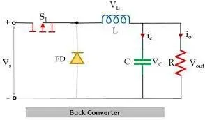
- Buck Converter:- The buck converter is the step down converter and produces a low voltage at the output side compared to the input side. fig shown below.
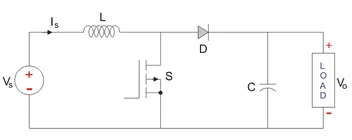
- Boost Converter:- The boost converter is the step up conveter and produced a high output voltage to the output side as compare to the input side. ifg shown below.
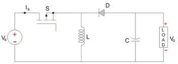
- Buck Boost Converter:- The buck boost converter can produced either high or low output voltage the the input voltage as per the requriment of the circuit. fig. shown below.
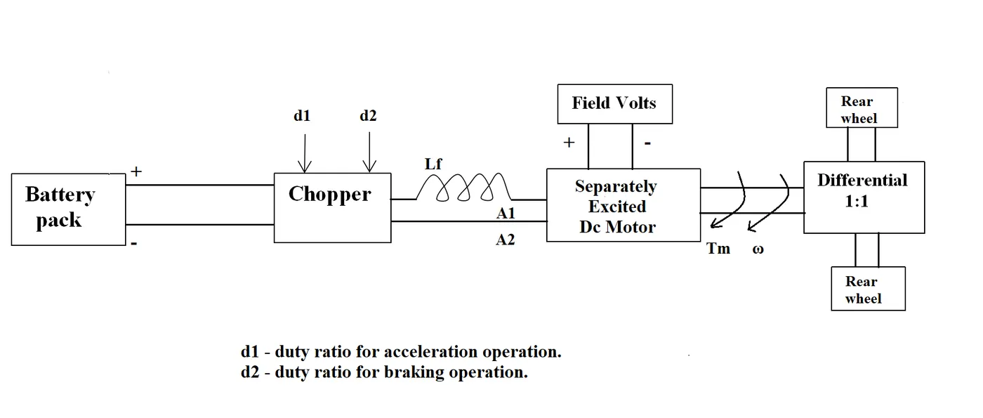
2. An Electric Vehicle's powertrain with 72V battery pack in shown in the diagram below. The duty ratio for acceleration operation is 'd1' and for the braking operation the duty ratio is 'd2'.
Given Data:-
Motor and Controller Parameters:
Rated Armature voltage= 72 V
Rated armature current= 400 A
Ra= 0.5Ω, KΦ= 0.7 Volt second
Chopper Switching frequency= 400 Hz
The vehicle speed-torque characteristics are given by the below equation

What is EV steady state speed if duty cycle is 70%?
we know that the torue equation
T = ((V*Kt)/Ra)-(((Kt^2)*w)/Ra)
T: Torque Nm
V: supply voltage
Ra: Resistance of armatur
Kt: Torque constant
w: angular velocity
so,
Tv = 24.7 + (0.0051)w^2 ..............eqn 1
Duty cycle is 70%
Va= 70/100*72
Va=50.4v for the steady state speed.
Put the Va valur in the torque equ.
T= ((50.4*0.7)/0.5)-(((0.7^2)*w)/0.5)
T=70.6-0.98w ..................equ 2
we have,
from equ 1 and eqn 2
T=Tv
70.56 - 0.98w = 24.7 + 0.0051w^2
70.56 - 24.7 -0.98w - 0.0051w^2 = 0
45.8 - 0.98w - 0.0051w^2 = 0
so we have to solve the quadratic equation
w1=38.87 w2=-231.02
Speed is always positive so we consider the positive value.
EV steady state speed is 38.87rad/s if duty cycle is 70%.
3. Develop a mathematical model of a DC Motor for the below equation using Simulink.
ω">ω= V/Kϕ">ϕ -Ra/Kϕ">ϕ^2.T
Let us draw a model for the above equation.
Let V = 50.4 Volts
Kϕ">Kϕ= 0.7
Ra">Ra= 0.50.5Ω">Ω
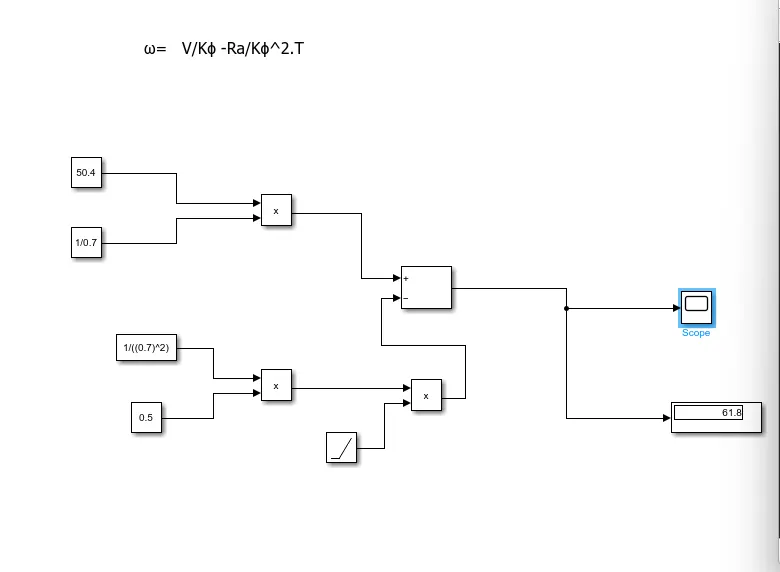
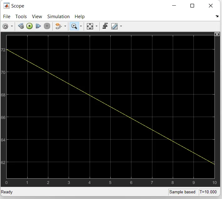
Above graph shows the DC motor characteristic.
4. Refer to the blog on below topic:
Induction Versus DC brushless motors by Wally Rippel, Tesla
Explain in brief about author’s perspective.
The case study by the author is exlpained below:-
DC brushless Motor:-
1. In the brushless motor permanent magnent are used for the producing the magnetic field.
2. Inverter required to run this motor. It is used for dc .
3. The brushless DC motor produces no starting torque when directly connected to fixed frequency utility power.
4.The DC brushless drive can also operate at unity power factor.
5.With DC brushless, as machine size grows, the magnetic losses increase proportionately and part load efficiency drops.
Induction Motor:-
1.There is no magnet used in the induction motor stacked steel laminations with buried peripheral conductors that form a “shorted structure are used.
2. the motor has the ability to start under load. No inverter is needed.
3. The fact that induction motors are directly compatible with conventional utility power is the main reason for their success.
4. The best power factor for the induction drive is about 85 percent. This means that the peak point energy efficiency for a DC brushless drive will typically be a few percentage points higher than for an induction drive.
5. For induction, as machine size grows, losses do not necessarily grow.
Further the author say there is no winner for that both the motor are efficient and capable for their best performance.