Project 1 - Interfacing a 16*2 LCD with Arduino using I2C protocol
Aim
To implement the Code for “Interfacing a 16*2 LCD with two Arduino’s (one for Master and one for Slave) using Inter-Integrated Circuit (I2C) communication protocol” by sending the message to LCD using I2C communication protocol and displaying the message on LCD screen
First, connect an Arduino uno R3 with an LCD display and display the message on it before doing the I2C communication between master and slave Arduino. For the same first we have to include liquidCrystal.h library.
The following steps are followed for the same
- Connect the VCC and GND of the LCD to the 5V and GND of the Arduino, respectively.
- Connect the LCD's RS (Register Select) pin to a digital pin on the Arduino (e.g., D7).
- Connect the RW (Read/Write) pin of the LCD to GND.
- Connect the LCD's EN (Enable) pin to a digital pin on the Arduino (e.g., D6).
- Connect the data pins D4 to D7 of the LCD to digital pins on the Arduino (e.g., D5 to D2).
- Connect the potentiometer's anode (longer lead) to 5V and the cathode (middle lead) to GND. Connect the wiper (variable lead) to the LCD's Vo (contrast) pin.
- Connect the backlight anode (A) and cathode (K) pins to 5V and GND if your LCD has backlighting.
Here on running the simulation, we see "Hello World" displayed on the LCD display
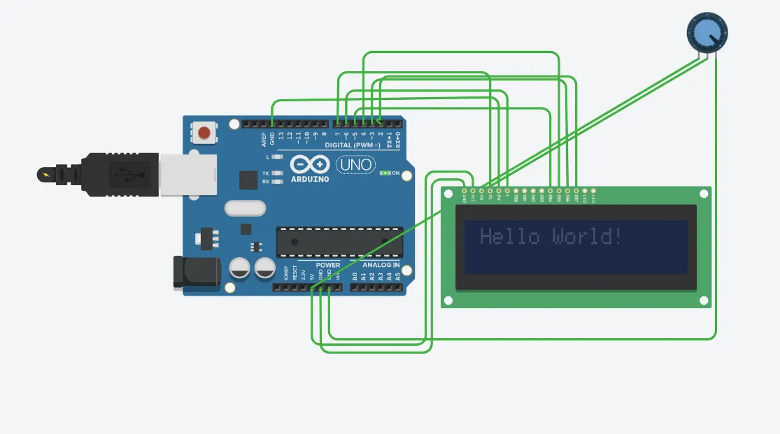
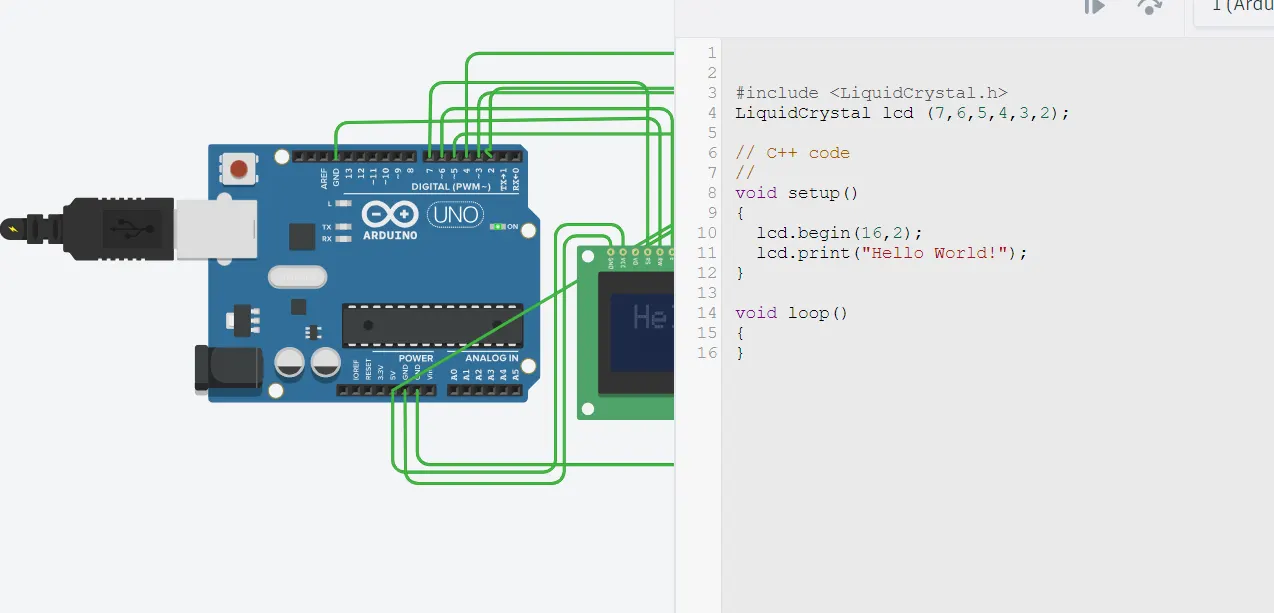
The circuit as well as the code for the same is displayed here in Figures 1 and 2. The potentiometer enhances the brightness of the font in display on changing the wiper
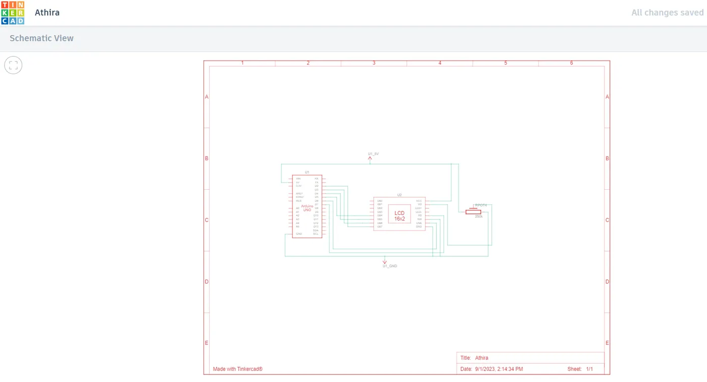
Figure 3 shows the schematic diagram for LCD display using Arduino
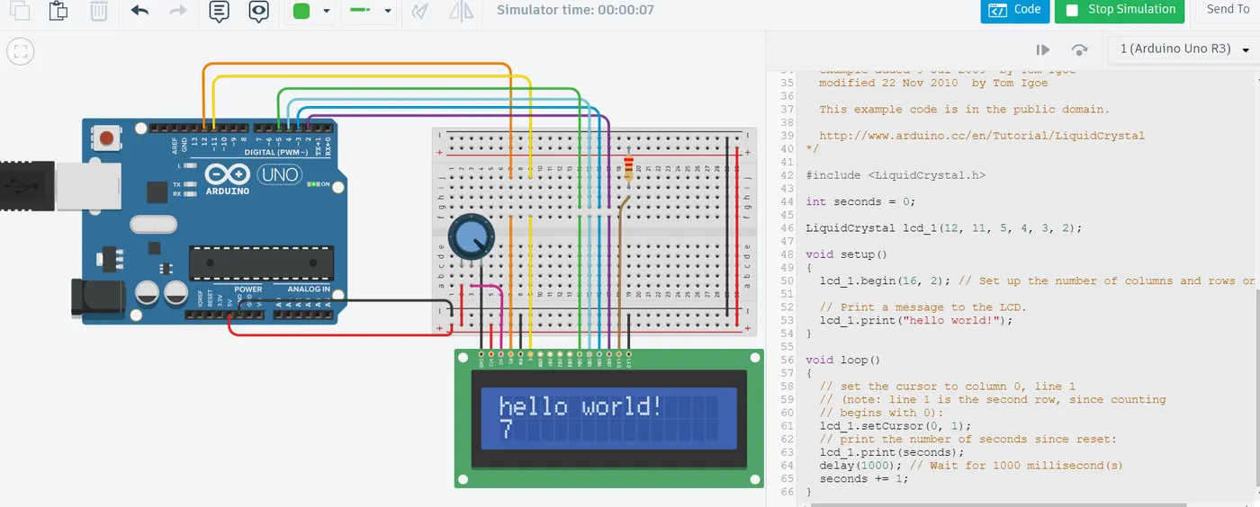
Figure 4 shows the existing program for LCD display in Tinkercad. Here along with printing Hello world the second are also counted.
I2C communication
I2C stands for inter-integrated circuit. It is a bus interface connection protocol incorporated into devices for serial communication The data is transferred in messages which are broken into frames of data. Each message has an address frame that contains the binary address of the slave and one or more data frames that contain the data being transmitted.
- For creating a master-slave setup with Arduino where the master Arduino communicates with the slave Arduino and both interact with an LCD display: Two Arduino Uno R3,16x2 LCD modules and jumper wires are required for the same.
The connections are done the following way
- Connect the VCC and GND of the LCD to 5V and GND of the Master Arduino, respectively.
- Connect RS, EN, D4, D5, D6, and D7 of the LCD to digital pins on the Master Arduino (e.g., D7, D6, D5, D4, D3, D2).
- Connect the SDA (A4) and SCL (A5) of the Master Arduino to the SDA and SCL of the Slave Arduino, respectively.
- Connect a 10kΩ pull-up resistor between SDA and 5V.
- Connect a 10kΩ pull-up resistor between SCL and 5V.
- Connect the VCC and GND of the LCD to 5V and GND of the Slave Arduino, respectively.
- Connect RS, EN, D4, D5, D6, and D7 of the LCD to digital pins on the Slave Arduino (e.g., D7, D6, D5, D4, D3, D2).
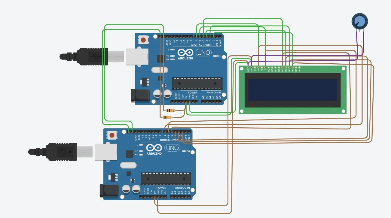
Figure 5 shows the master-slave Arduino connection diagram using I2C and figures 6 and 7 are the respective codes for master and slave
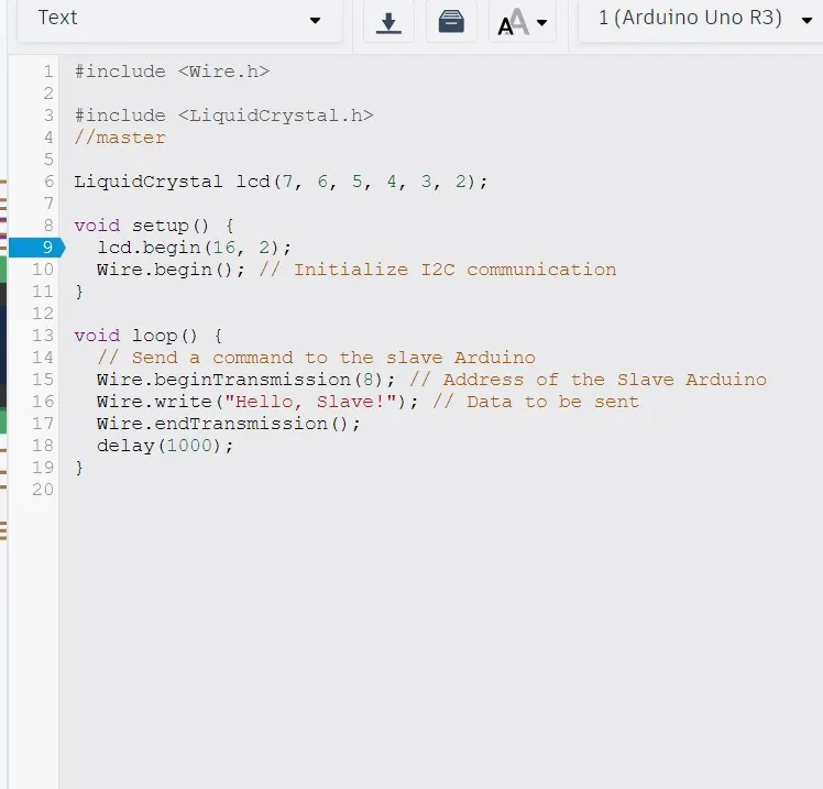
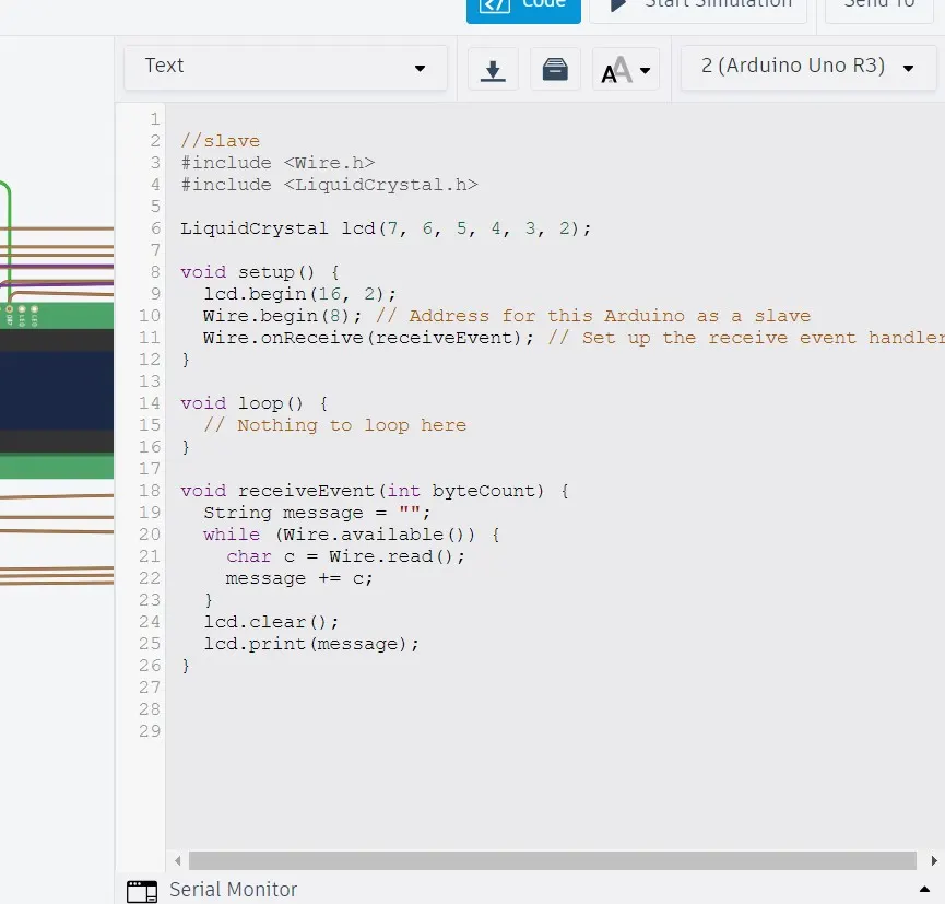
The code for the above program is shown below. Here I2C communication is initialised and the display is made ready by setting the cursors at the right place. Liquid crystal. h as well as wire.h library is included for LCD display as well as I2C communication. Here Arduino1 is the master and Arduino 2 is the slave. Messages are transmitted and received between the Arduino and are displayed on the LCD
#include
#include
//master
LiquidCrystal lcd(7, 6, 5, 4, 3, 2);
void setup() {
lcd.begin(16, 2);
Wire.begin(); // Initialize I2C communication
}
void loop() {
// Send a command to the slave Arduino
Wire.beginTransmission(8); // Address of the Slave Arduino
Wire.write("Hello, Slave!"); // Data to be sent
Wire.endTransmission();
delay(1000);
}
//slave
#include
#include
LiquidCrystal lcd(7, 6, 5, 4, 3, 2);
void setup() {
lcd.begin(16, 2);
Wire.begin(8); // Address for this Arduino as a slave
Wire.onReceive(receiveEvent); // Set up the receive event handler
}
void loop() {
// Nothing to loop here
}
void receiveEvent(int byteCount) {
String message = "";
while (Wire.available()) {
char c = Wire.read();
message += c;
}
lcd.clear();
lcd.print(message);
}
The schematic diagram for connections is shown in the figure 8
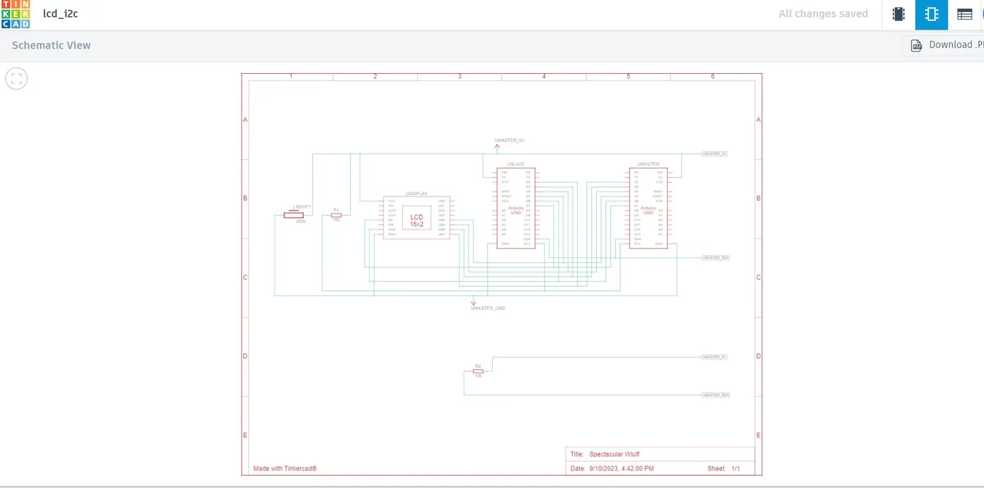
But for this system even though master slave I2C communication is happening the circuit is complicated due to the connection of all pins making one confused. So we can rectify this issue using a liquidcrystali2c library and do the code.
For this, we have to do the following connections
- GND to GND
- VCC to 5V
- SDA to A4 (for Arduino Uno)
- SCL to A5 (for Arduino Uno)
- SDA of master Arduino to SDA of slave Arduino
- SCL of master Arduino to SCL of slave
- Both Arduino should have a common ground reference
- Wire.beginTransmission() and Wire. write() functions are used in Master to send data to the slave Arduino
- Delay for a second between transmissions In slave I2C communication is analyzed Wire. begin and register the receive Event function handle incoming data.
The code for the master Arduino is
//master
#include
#include
LiquidCrystal_I2C lcd(0x27, 16, 2); // Initialize the LCD with I2C address 0x27
void setup() {
Wire.begin(); // Initialize I2C communication as a master
lcd.init(); // Initialize the LCD
lcd.backlight(); // Turn on the backlight
lcd.setCursor(0, 0);// Set the cursor to the top left corner
lcd.print("Master"); // Print on the LCD
Serial.begin(9600); // Initialize serial communication
}
void loop() {
Wire.beginTransmission(9); // Address of the slave Arduino
Wire.write("Hello, slave!"); // Send data to slave
Wire.endTransmission(); // Stop transmitting
delay(1000); // Delay for a second
}
The code for the slave Arduino is
//slave
#include
#include
LiquidCrystal_I2C lcd(0x27, 16, 2); // Initialize the LCD with I2C address 0x27
void setup() {
Wire.begin(9); // Initialize I2C communication as a slave with address 9
Wire.onReceive(receiveEvent); // Register the receive event
lcd.init(); // Initialize the LCD
lcd.backlight(); // Turn on the backlight
lcd.setCursor(0, 0); // Set the cursor to the top left corner
lcd.print("Slave"); // Print on the LCD
Serial.begin(9600); // Initialize serial communication
}
void loop() {
}
void receiveEvent(int bytes) {
while (Wire.available()) {
char receivedChar = Wire.read(); // Read the incoming data
lcd.setCursor(0, 1); // Set the cursor to the second line
lcd.print(receivedChar); // Display received data on the LCD
Serial.print("Received: ");
Serial.println(receivedChar);
}
}
The circuit setup is shown below
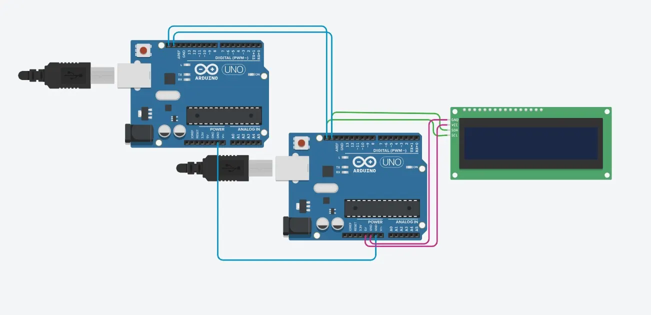
To display in an LCD using Mater slave Arduino via I2C communication is done.