Project 1 - Controlling a DC motor using PWM and monitoring its Running status
Project 1 Live batch 9
Aim: Implement a system on the simulator for controlling a DC motor using L293 motor driver, monitor its status and print the running status of motor on the LCD Display
DC Motor
- A DC motor is any of a class of rotary electrical motors that converts direct current (DC) electrical energy into mechanical energy
- The most common types rely on the forces produced by magnetic fields
- Nearly all types of DC motors have some internal mechanism, either electromechanical or electronic, to periodically change the direction of current in part of the motor
L293 Motor Driver
- The L293D is a popular 16-Pin Motor Driver IC
- A single L293D IC is capable of running 2 DC motors at the same time; also the direction of these two motors can be controlled independently
- Motors which has operating voltage less than 36V and operating current less than 600mA, which are to be controlled by digital circuits like Op-Amp,555 timers, digital gates or even Microcontrollers like Arduino, PIC, ARM etc , thiss IC is used
- The IC works on the principle of Half H-Bridge
Code
#include <avr/io.h>
#define F_CPU 16000000UL
#include "avr/interrupt.h"
#include <util/delay.h>
#define sw_dir (PIND&(1<<1)) //D1 pin as push button for direction control
#define sw_spd (PIND&(1<<2)) // D2 pin as push button for speed control
#define pw (PINC&(1<<3)) // C3 pin as push button for power on/off
#define lcd_port PORTB //PORTB for lcd data
#define RS_high PORTD|=(1<<5) //D5 pin for RS
#define RS_low PORTD&=~(1<<5)
#define EN_high PORTD|= (1<<6) //D6 pin For EN
#define EN_low PORTD&=~ (1<<6)
unsigned char i; //variable declared to increase the duty cycle in PWM
void lcd_cmd(char cmd)
{
lcd_port=(cmd&0xf0);
RS_low;
EN_low;
_delay_ms(1);
EN_high;
lcd_port=((cmd<<4)&(0xf0));
RS_low;
EN_low;
_delay_ms(1);
EN_high;
}
void lcd_data (char data)
{
lcd_port=(data &0xf0);
RS_high;
EN_low;
_delay_ms(1);
EN_high;
lcd_port=((data <<4)&(0xf0));
RS_high;
EN_low;
_delay_ms(1);
EN_high;
}
void lcd_init()
{
lcd_cmd(0x02);_delay_ms(5); //return the cursor to home
lcd_cmd(0x01);_delay_ms(5); //clear screen
lcd_cmd(0x0C);_delay_ms(5); //display on cursor off
lcd_cmd(0x06);_delay_ms(5); //increment cursor
lcd_cmd(0x80);_delay_ms(5); //force cursor to begin first line
lcd_cmd(0x28);_delay_ms(5); //used for 4 bit lcd mode
}
void cursorpos(char x, char y)
{
if((x<1||x>2)||(y>16||y<1))
{
x=1;
y=1;
}
if(x==1)
{
lcd_cmd(0x7f+y);
}
else
{
lcd_cmd(0xBF+y);
}
}
void lcd_out(char x, char y , char * str)
{
cursorpos(x,y);
while(*str)
{
lcd_data(*str);
str++;
}
}
int main(void)
{
DDRB=0xff; // set output
DDRA|=((1<<0)|(1<<1)); //declaring A0 A1 as output
DDRD&=~(1<<1); //declaring D1 as input
DDRD&=~(1<<2); //declaring D2 as input
DDRD|=(1<<5); //declaring D5 as output
DDRD|=(1<<6); //declaring D6 as output
DDRC&=~(1<<3); //declaring C3 as input
PORTD|=(1<<2); //enable internal pull up resistor for D2
PORTC|=(1<<3); //enable internal pull up resistor for D3
i=64; //motor @25% duty cycle
TCCR0=0x61; // non inverting, PWM phase correct, no pre scalar
GICR=(1<<INT0);
MCUCR=0x02; //interrupt negative edge trigger
sei(); //enable global interrupt
lcd_init(); //intialise output
/* Replace with your application code */
while (1)
{
while(pw==0)
{
if (sw_dir==0)
{
PORTA =0b00000001; //clockwise
lcd_out(1,1,"Motor is running");
lcd_out(2,3,"clockwise");
}
else
{
PORTA =0b00000010; //anticlockwise
lcd_out(1,1,"Motor is running");
lcd_out(2,3,"anticlockwise");
}
OCR0 =i; // value load as i increases
}
PORTA =0X00; //stop rotation
lcd_out(1,1,"Motor is off");
lcd_out(2,3,"!!!CAUTION!!!");
}
}
ISR(INT0_vect) // interrupt service routine
{
i=i+20; //value loaded
}
Figures 1-5 shows the program code for running motor clockwise and anticlockwise using L293 driver
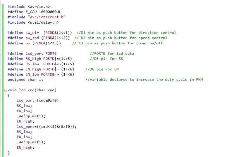
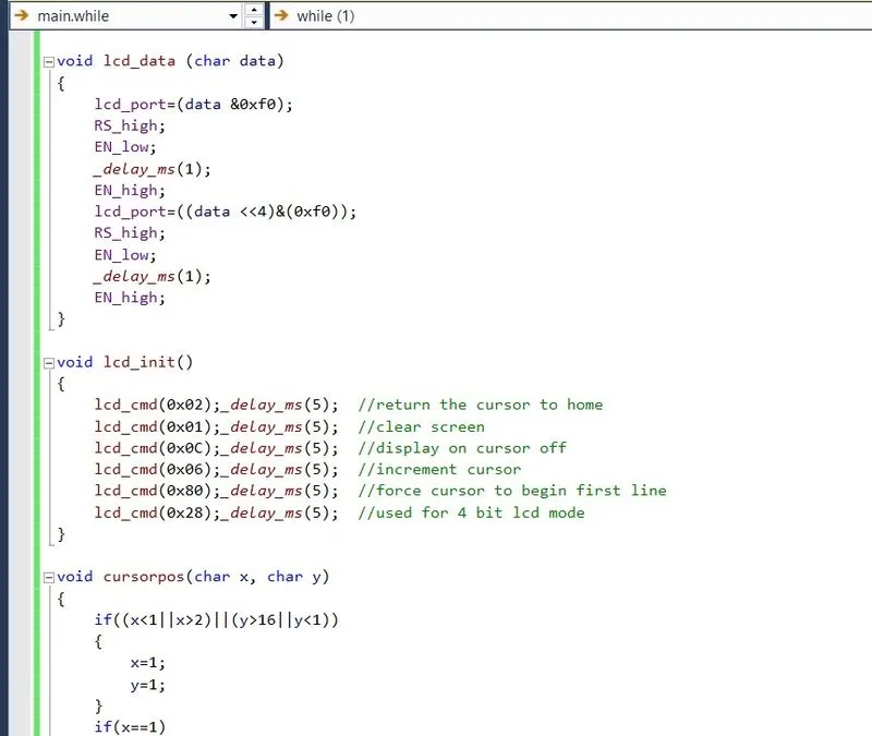
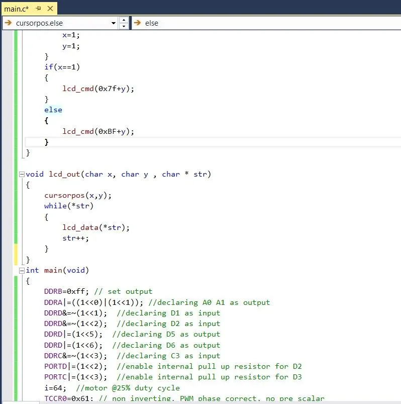
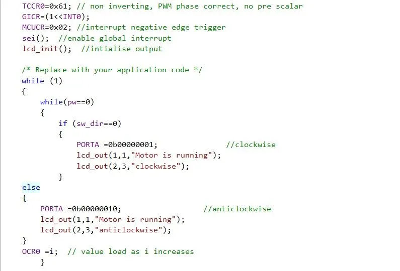
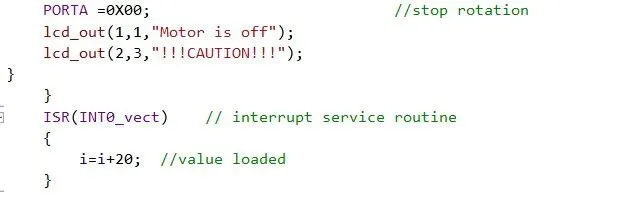
Figure 6 shows the motor running in clockwise direction
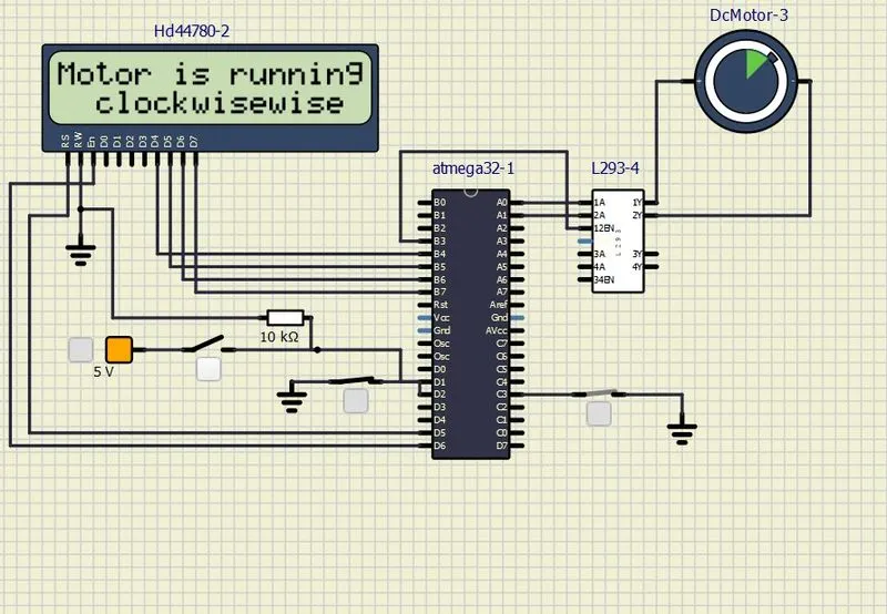
Figure 7 showing motor control in anticlockwise direction
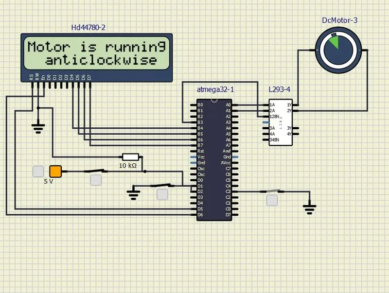
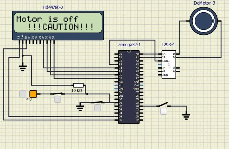
Figure 8 shows caution message
Comments
- PORTD, D1 pin as push button for direction control and D2 pin as push button for speed control
- PORTB set as output
- PORTC ,C3 pin as push button for power on/off
- D5 and D6 is used for setting RS and EN
- Initialization of lcd is done through lcd_init function
- Interrupt service routine is enabled
- Internal pull up resistors are enabled for D2 and D3
- Global interrupt is enabled and cursor positions are set
- Motor is made to run at 25%duty cycle by selecting i=64
- Timer registor is set non inverting with no pre scalar
- Motor run continuously as value loaded continuously though while loop
- Motor is made to run clockwise , anticlockwise and is turned off with a caution ,thus controlling motor speed , direction and turn on and off usinf L293 IC driver and motor operation is observed
Result
- Implemented a system on simulator to control a DC motor using PMW
- Controlling the speed of the DC motor using PMW
- Monitoring the running status of the DC motor using L293 motor driver which allows the DC motor to drive on any direction
- Running status i.e. on which direction the DC motor is running is to be displayed on the LCD screen.