Project 1 (Mini Project on Vehicle Direction Detection
Mini Project on Vehicle Direction Detection
Objective of Mini Project:
- Development of MATLAB Simulink model as per requirement.
- Tag the requirements to the simulink model; tagging requirement 1 & requirement 2 to their corresponding subsystems is fine.
- MBD compliant changes, Data Dictionary creation & code generation is added advantage, and that is not scope of this project.
- If choosing code generation, Storage class for Input signals: ImportedExtern; Storage class for Output signal: Export to File; Storage class for local signals: localizable; Storage class for calibration signals: Const.
- Choose sample time for all signals as 0.01s.
The following steps are to be followed to do the project
- Development of Matlab Model
- Requirement Tagging
- Linking of the Simulink Data Dictionary
- Signal resolving and Signal Propagation for Input and Output
- Configuration Parameter Settings
- Model Advisor Report Generation
- Code generation
1) To develop MATLAB Simulink Model
- Identifying the direction of the vehicle is taken based on the camera input.
- The camera reads the road signs & stores them in its memory with unique values for the left turn, right turn & straight drive.
- Depending on the direction it is taking, the final indication is given to the driver – as an indication if he is driving in the recommended direction or not.
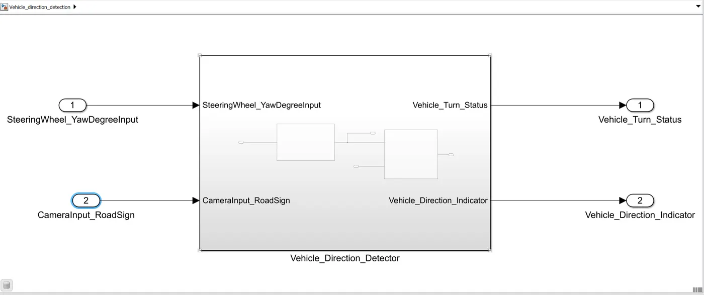
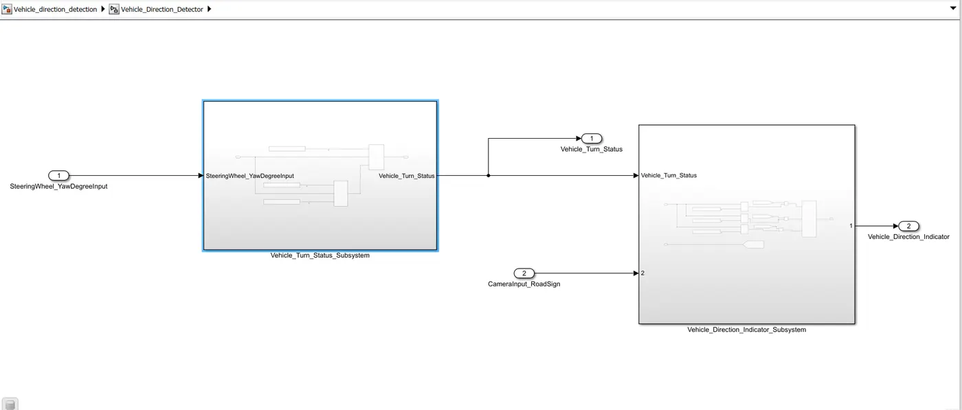
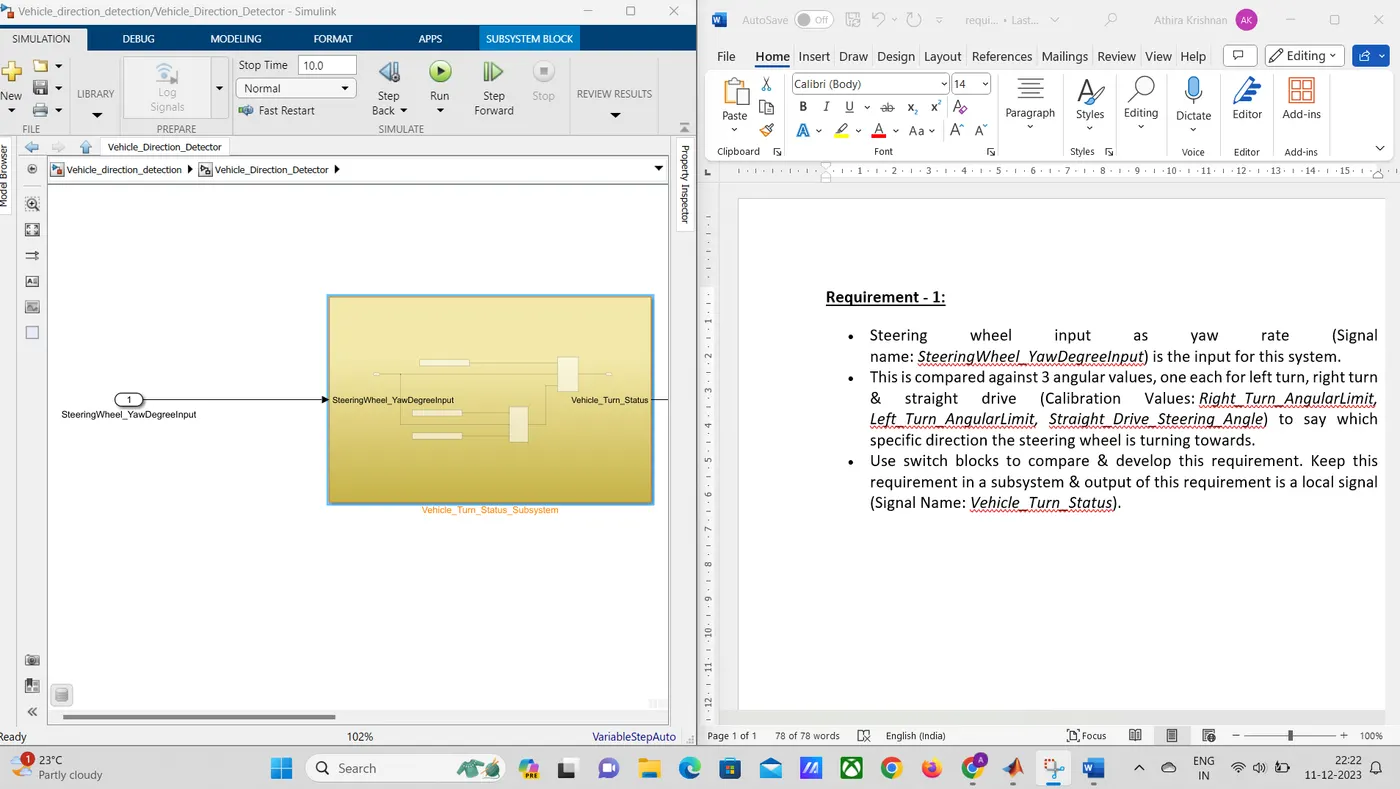
Requirement 1:
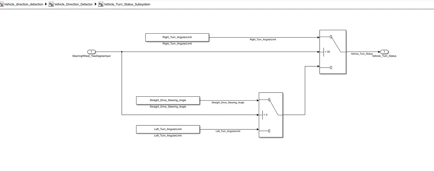
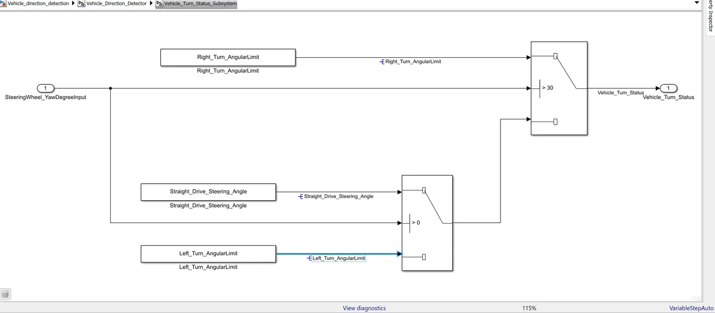
- The yaw rate of the steering wheel is kept as the input and compared with the 3 angular values for the left turn, right turn, and straight drive respectively specific to the direction the steering wheel is turning which can be achieved using switch blocks.
- The yaw rate is compared with the Right_Turn_Angularlimit which is 30. The right turn value is passed if the input is equal to or greater than 30 and the 2nd condition passes if the input is less than 30. Left_turn or Straight_Drive is passed if the input is zero.
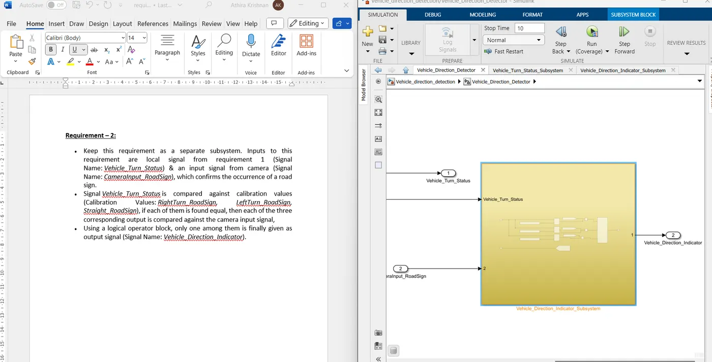
Requirement 2 :
- For requirement 2, the output of the first subsystem Vehicle_Turn_Status is provided as the input alongside CameraInput_RoadSign to the second system.
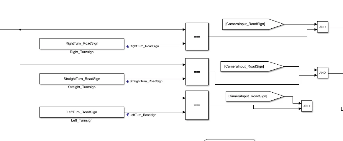
- Here the Vehicle_Turn_Status is compared with calibration values RightTurn_RoadSign, LeftTurn_RoadSign, Straight_RoadSign using compare to constant block
- The values are passed on to the Logical operator AND where the final output is delivered by comparing with camera input and it indicates the direction of the vehicle and is called Vehicle_Direction_Indicator.
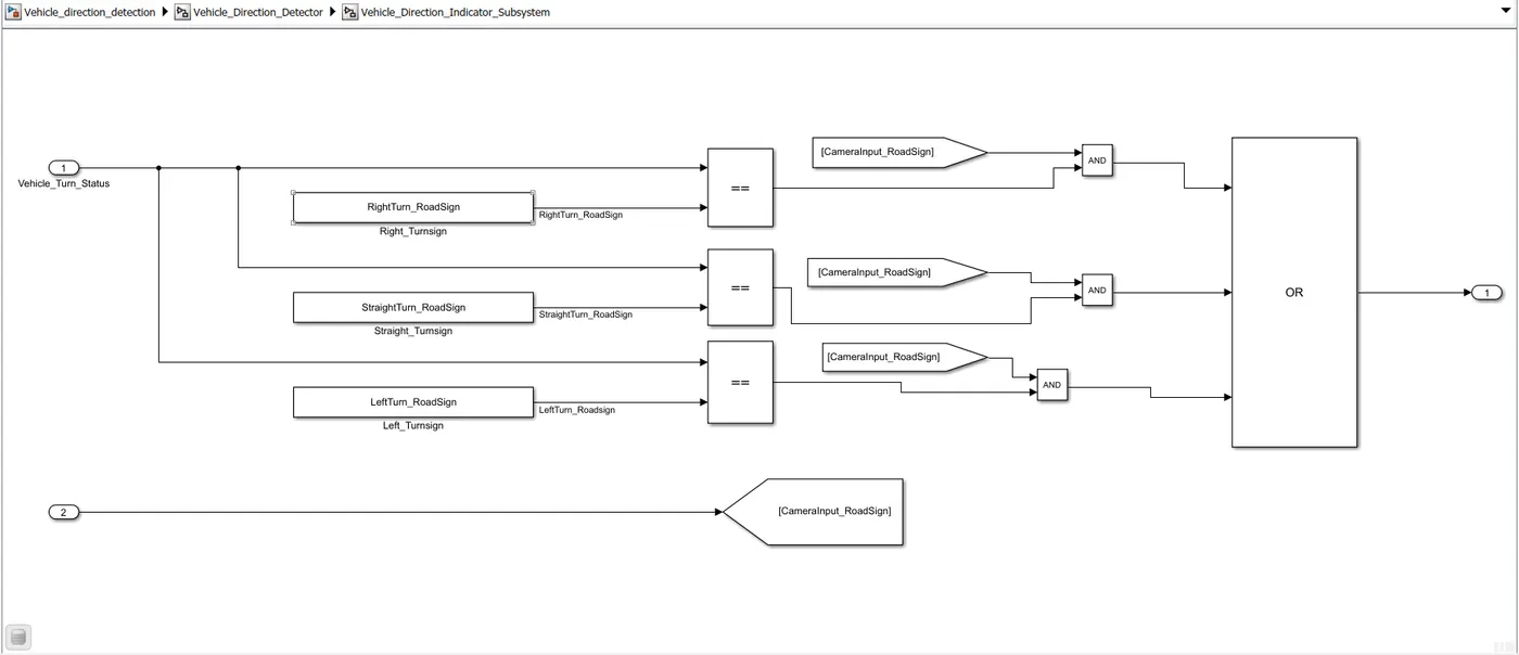
Here we can see that the input from the previous subsystem will be compared with 3 compared to constant blocks and the output of which will be compared with the camera input using the logical operators. The AND signal will give us the selected output required and it will be collected using the OR operator.
2) The second step is to tag the requirements in the model with the requirement datasheet.
An MS Word document is created including both the requirements as per the question
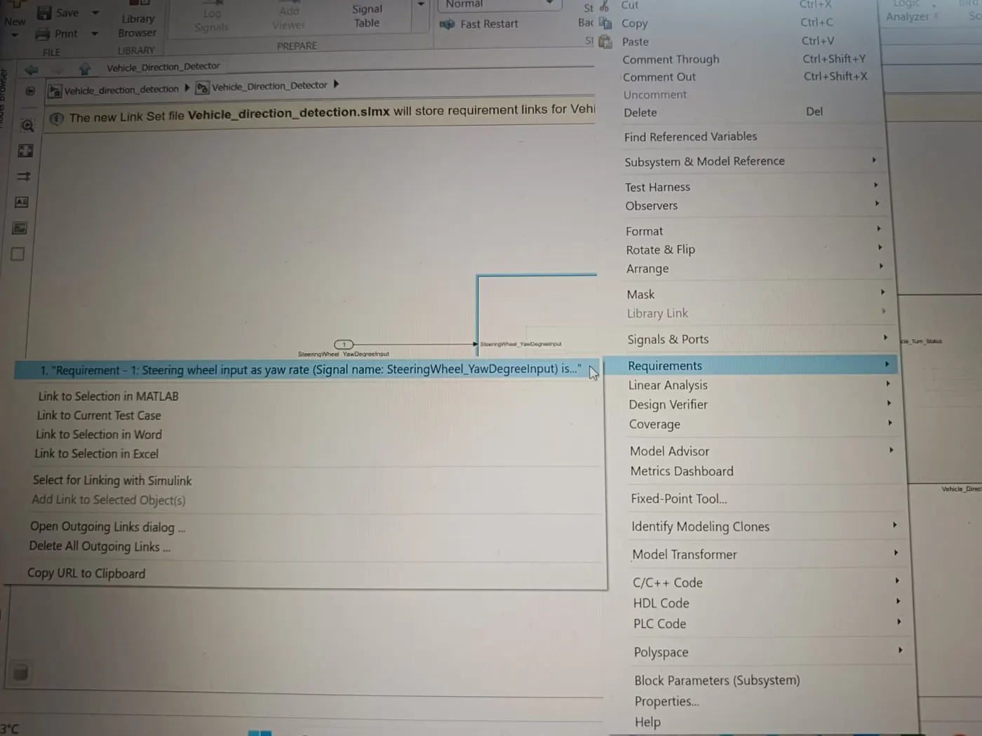
- The statement to be linked is selected right-click on the required subsystem and then go to requirements and then click on the link to select in Word. A new .slmx file will be created in the path selected and the links will be stored in that file.
- The respective subsystems tagged with the requirements are shown below:
Requirement 1:
Requirement 2:
3) Linking of the Simulink Data Dictionary
- To create an SLDD file for the model, the table of details regarding the signals and calibration value given is referred.
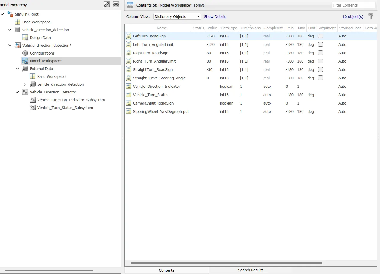
- A file is created and we open the link add the given input and output signals, and then add the calibration values. The data dictionary created is shown below:
Signals & Calibration Data List:
|
Signal / Calibration Name |
Signal Type |
Data Type |
Dimension |
Min |
Max |
Initial Value |
Units |
|
SteeringWheel_YawDegreeInput |
Input |
Int16 |
1 |
-180 |
180 |
- |
Deg |
|
CameraInput_RoadSign |
Input |
Boolean |
1 |
0 |
1 |
- |
- |
|
Vehicle_Turn_Status |
Local |
Int16 |
1 |
-180 |
180 |
- |
Deg |
|
Right_Turn_AngularLimit |
Calibration |
Int16 |
[1 1] |
-180 |
180 |
30 |
Deg |
|
Left_Turn_AngularLimit |
Calibration |
Int16 |
[1 1] |
-180 |
180 |
-120 |
Deg |
|
Straight_Drive_Steering_Angle |
Calibration |
Int16 |
[1 1] |
-180 |
180 |
0 |
Deg |
|
RightTurn_RoadSign |
Calibration |
Int16 |
[1 1] |
-180 |
180 |
30 |
|
|
LeftTurn_RoadSign |
Calibration |
Int16 |
[1 1] |
-180 |
180 |
-120 |
|
|
Straight_RoadSign |
Calibration |
Int16 |
[1 1] |
-180 |
180 |
0 |
|
|
Vehicle_Direction_Indicator |
Output |
Boolean |
1 |
0 |
1 |
- |
- |
- The Sldd file is created and linked to the model.
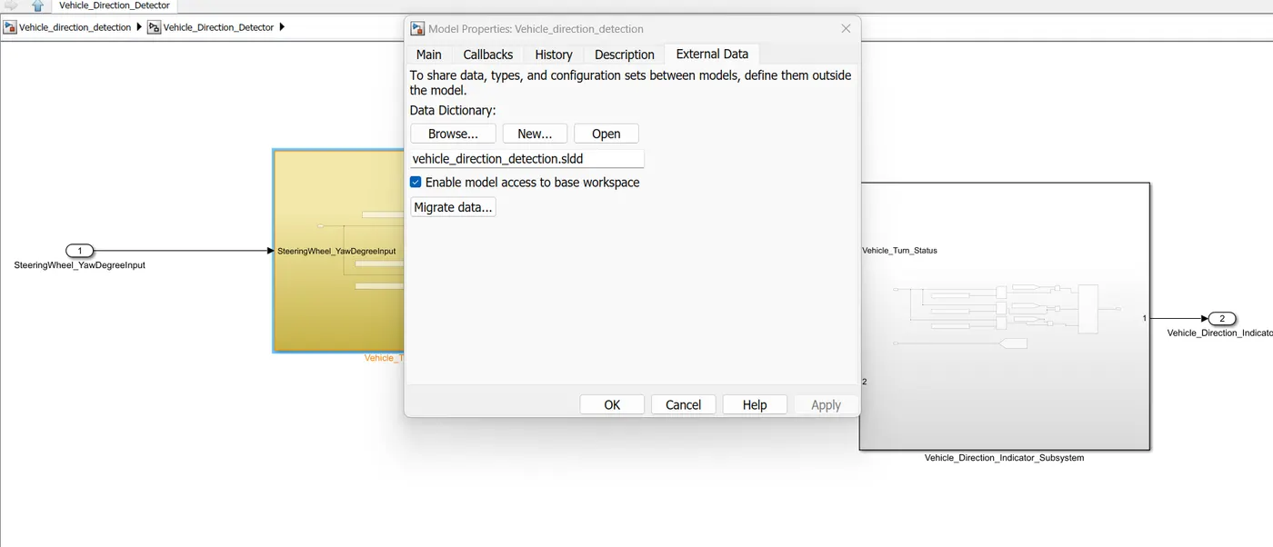
The parameters and input and outputs are classified as simulink parameters and Signals and data are filled accordingly w.r.t the table given.
4) Signal resolving and Signal Propagation for Input and Output
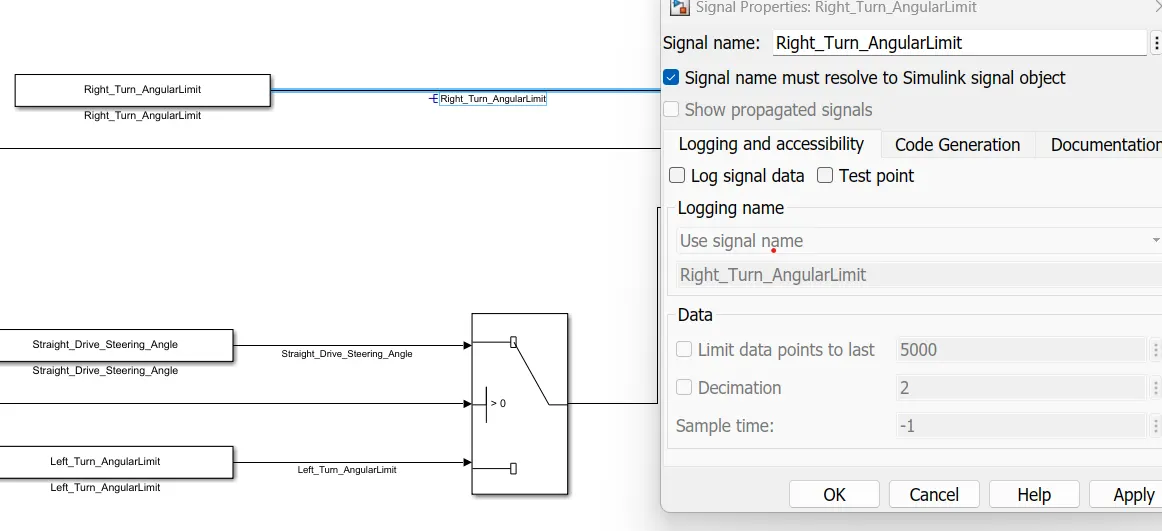
- Once the SLDD file has been created, we can resolve the signal name to the Simulink signal object as shown below
- For the same select the signal choose properties and enable signal name resolve to simulink signal object
- This allows the model to take the signal values during the simulation and the signal is shown below:
5) Configuration Parameter Settings
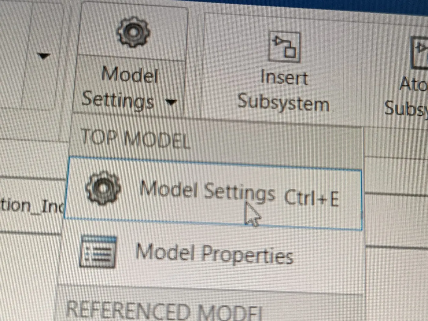
For configuration settings, we select model settings unlike model properties selected for sldd creation.
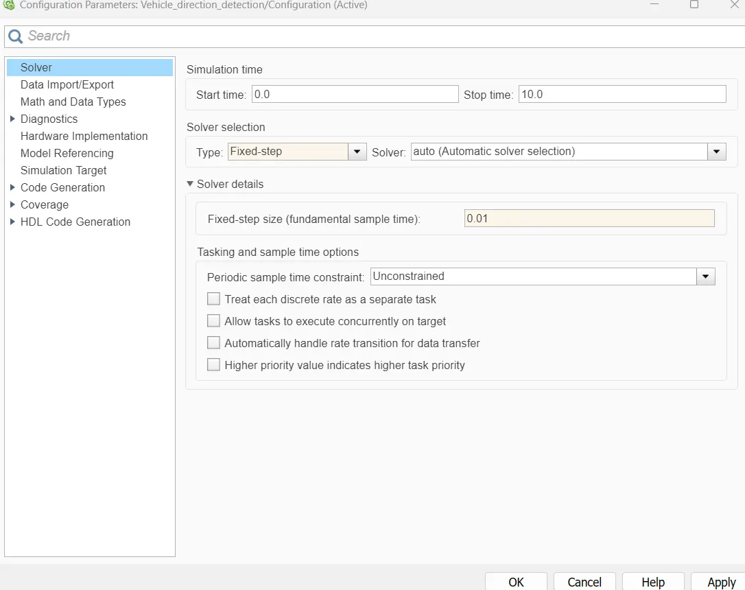
- First the solver is selected, and the start and stop times are set at 0 and 10s respectively.
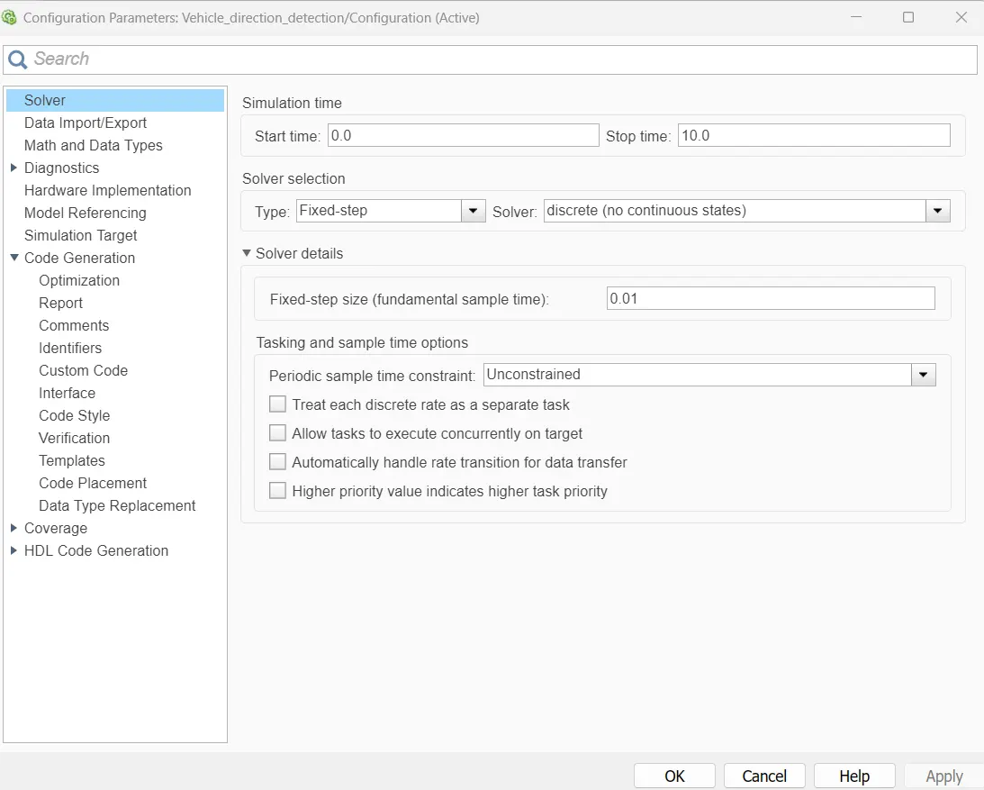
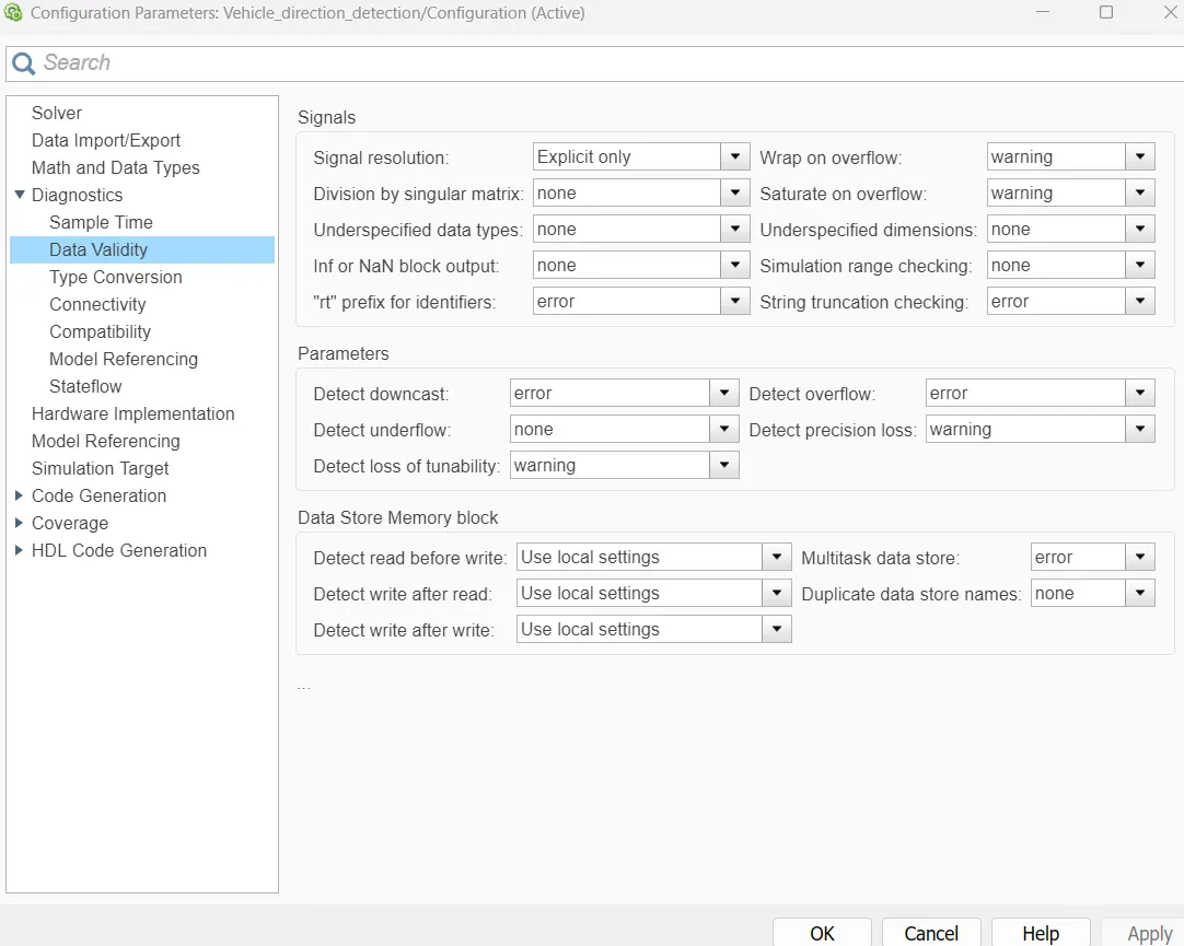
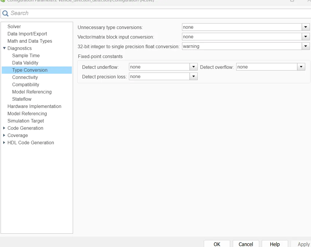
- In diagnostics, the warnings and none are changed to error
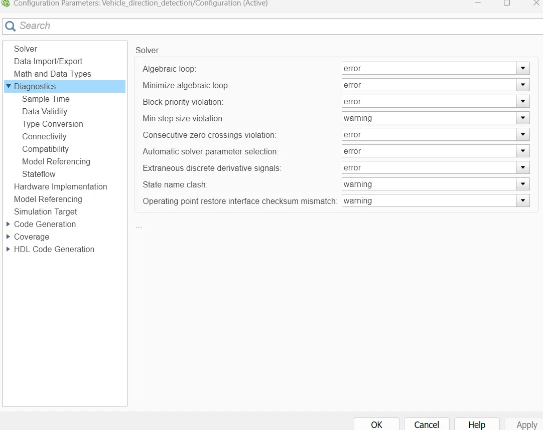
- All the parameters in sample time are also set to error
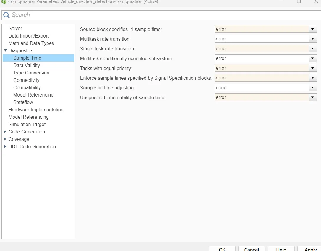
- Data validity, type conversion, connectivity,model referencing as well as Stateflow is maintained in same manner.
- For Hardware implementation, the device vendor is selected as intel and the device type is x86-64.
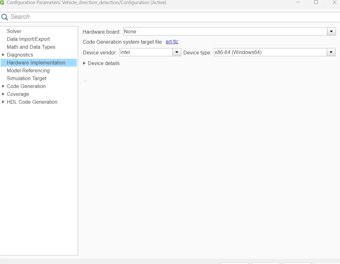
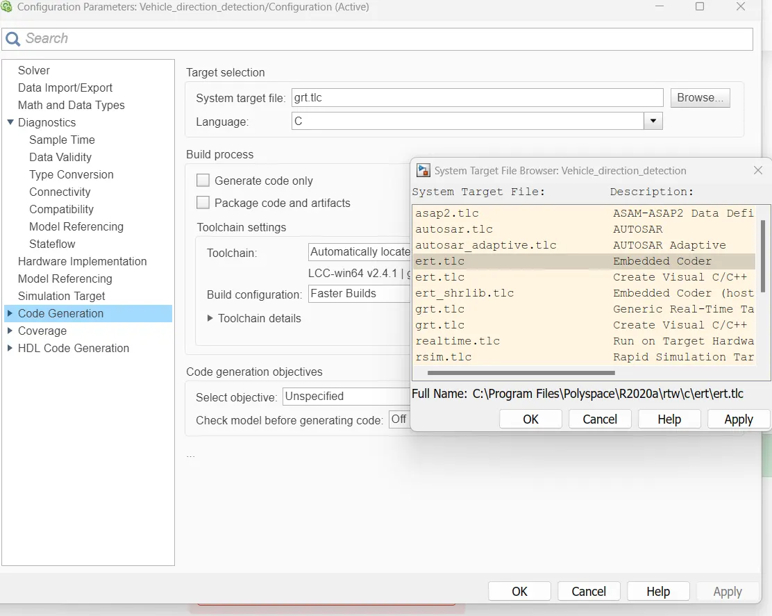
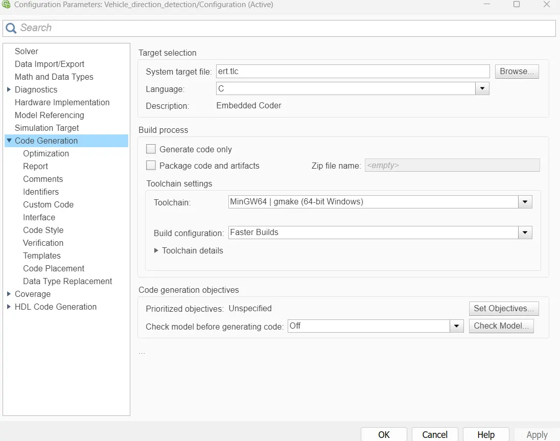
- For code generation grt. tlc is changed to ert.tlc
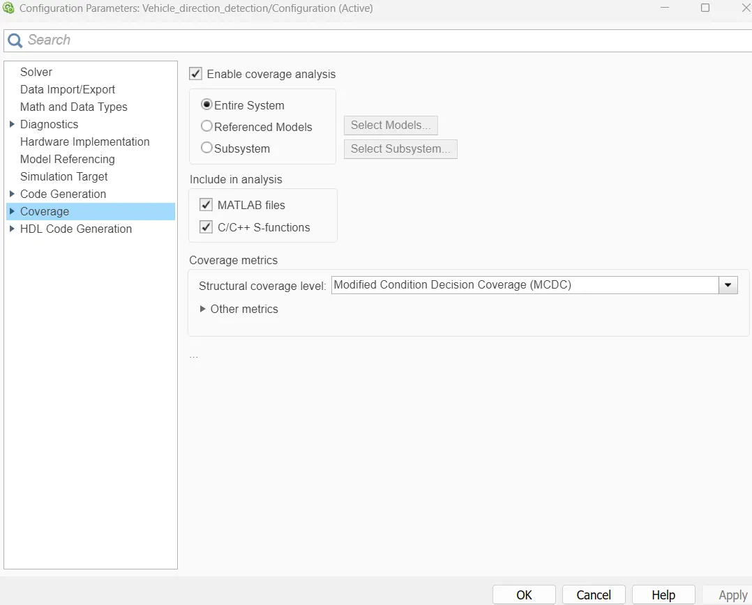
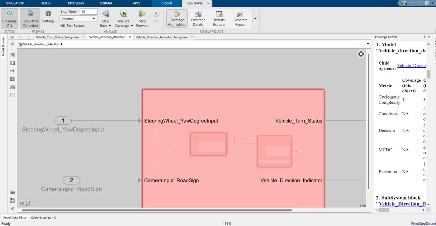
- Coverage analysis is enabled for the entire system
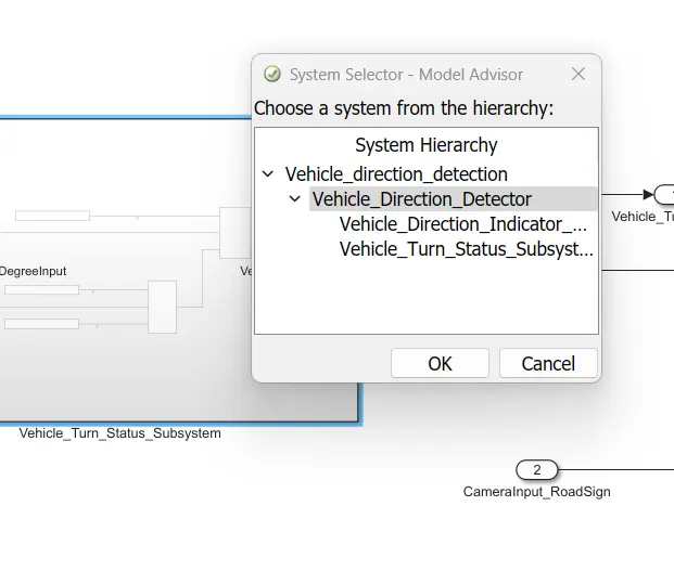
6) Model Advisor Report Generation
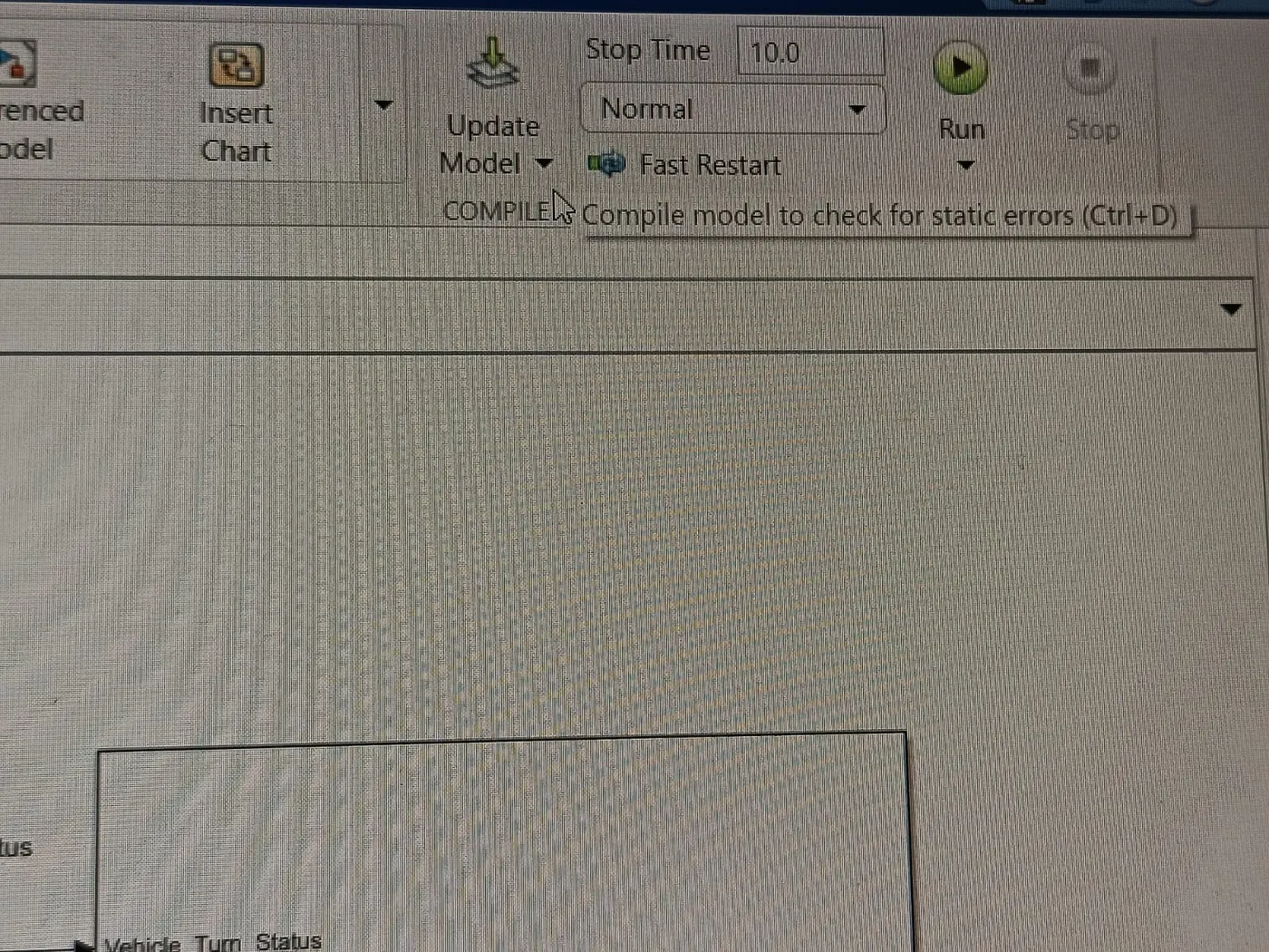
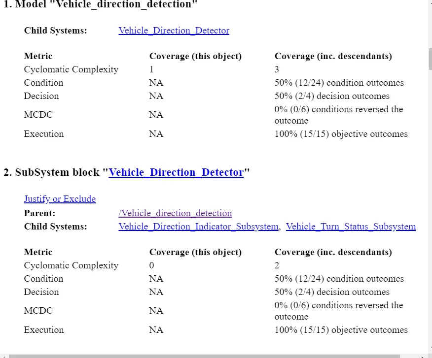
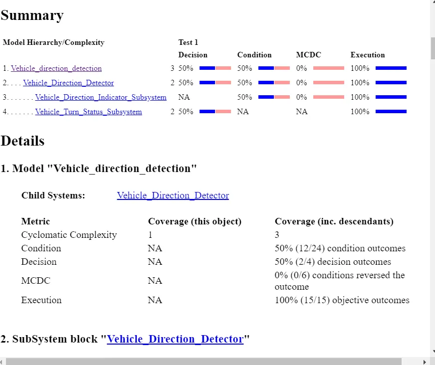
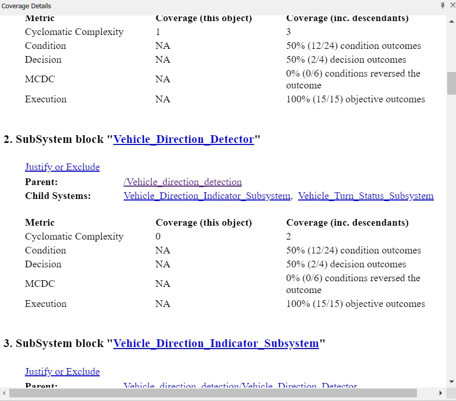
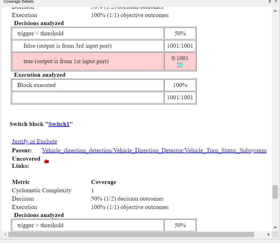
- The model was updated using CTRL+D before running the coverage analysis.
- The model was run and the model advisor report was generated.
7) Code Generation
- A code for the model is generated which helps to generate an S function block that helps test the model.
- For this, while setting the configuration parameters, the model format is changed to ert. tlc instead of grt. tlc.
- After which go to the APPS tab and click on the Build option in the embedded coder to get the code for vehicle direction detection.
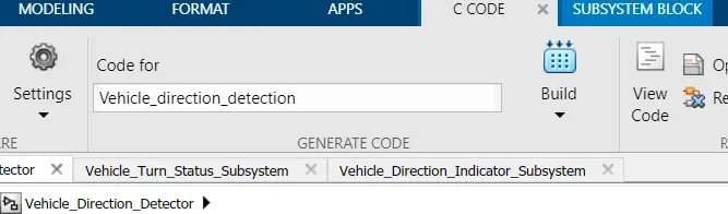
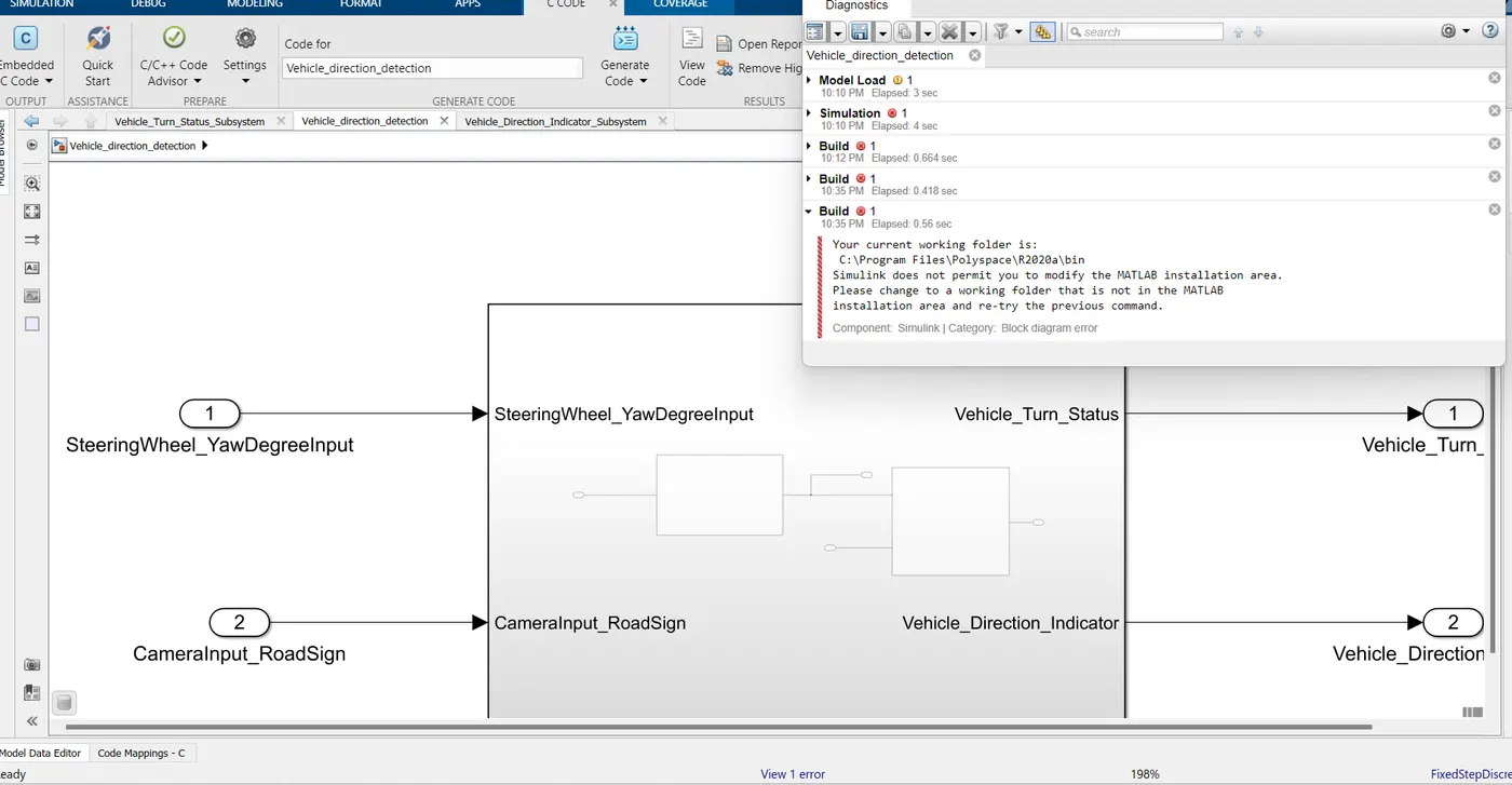
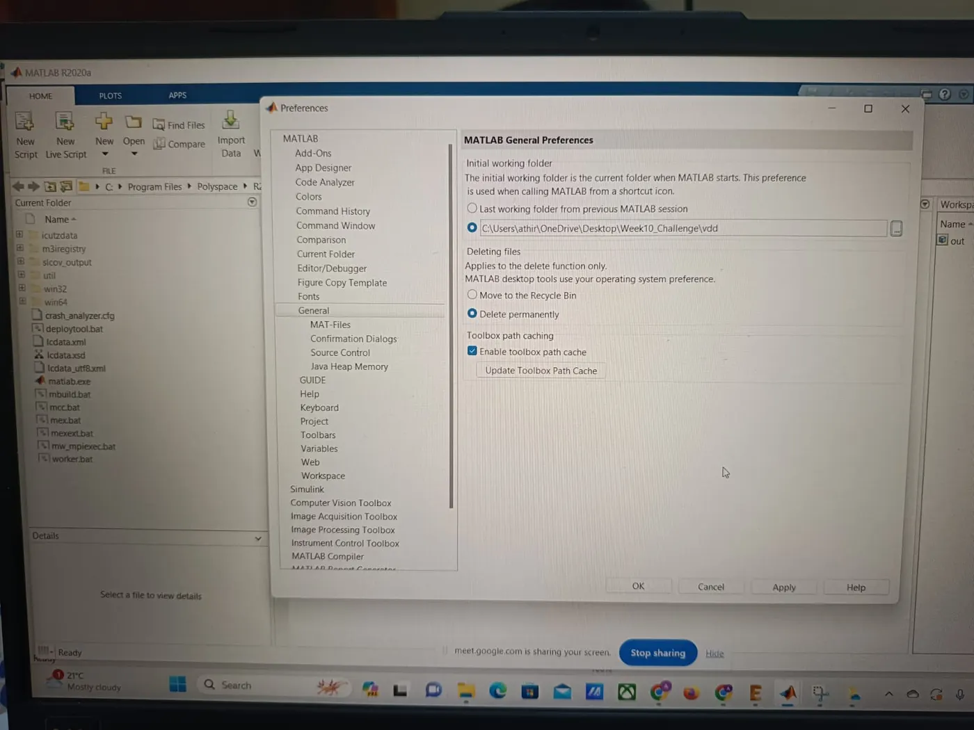
There was an error generating the code, suggesting to modify the working folder, even though after many tries and discussion with mentor as well as changing the folder path the code was not generated
Results
- The vehicle direction detection is modeled as per the requirement.
- All signals are defined in the Simulink data dictionary.
- The input as well as output signals are resolved and propagated.
- Updated the model using CTRL+D to check for static errors.
- Run the model advisor tool to see any errors and a report is generated and no errors were reported.
- Code generation is followed after the model is made to run.