Project
Aim
To study and analyze BAJA All Terrain Vehicle(ATV) model by carrying out a system level simulation of all terrain vehicle and differentiate between models.
To download the model from the given link and understand the functions of various blocks and subsystems employed in the given model and to compare with the different models provided
All Terrain Vehicle
- All Terrain Vehicle (ATV) also known as Light Utility Vehicle (LUV) is a vehicle that travels on low pressure tires with a seat that is straddled by the operator and with handlebars for steering control.
- It is designed to travel on all types of ground including rough grounds ie capable to handle wider variety of terrain than most other vehicles.
ATVs divided into two types:
- Type 1 - Intended by the manufacturer for use by a single operator
- Type 2 - Intended by the manufacturer for use by an operator and a passenger and these are equipped with a seating position behind operator.
BAJA SAE
- Collegiate design series competition run by the Society of Automotive Engineers International(SAE International).
- The goal in Baja SAE racing is to design, build and race off-road vehicles that can withstand the harshest elements of rough terrain.
- The vehicles used in Baja SAE racing are often similar in appearance to dune buggies.
Continuously Variable Transmission (CVT)
- Automatic transmission that can change seamlessly through a continuous range of gear ratios.
- Allow the engine to operate at constant rpm while the vehicle moves at varying speeds with suitable control.
- Common types of CVT uses 2 pulleys connected by belt or chain.
Types of model studied
- BAJA ATV model without dashboard(cvtModel)
- BAJA ATV model- Data Extraction (cvtModel_data)
- BAJA ATV model with dashboard (cvtModel_dashboard)
- BAJA ATV model with cvt ratio rpm (cvtModel_cvtratio_rpm)
- BAJA ATV model mapped lookup table without dashboard (cvtModel_mapped)
- BAJA ATV model - mapped lookup table with dashboard(cvtModel_dashboard_mapped)
Blocks used
- Generic Engine block- Connections F and B are mechanical rotational conserving ports associated with the engine crankshaft and engine block. Connections P and FC are physical signal output ports .
- Variable ratio transmission block - The physical signal input r defines the ratio of input to output angular shaft velocities. Connections B (base) and F (follower) are mechanical rotational conserving ports.
- Vehicle body block -Represent a 2 axle vehicle body in longitudanal motion.
- Double shoe brake block - Brake arranged as 2 pivoted rigid shoes symmetrically installed inside or outside drum operated by actuator
- Solver configuration, Signal builder, Constant, Scope, Circular guage,Rpm sensor,Inertia, Goto, From, Integrator, PS to simulink converter, Mechanical reference.
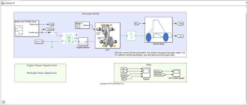
1) BAJA ATV model without dashboard(cvtModel)
Figure 1 shows the simulink model of model without dashboard
- Most of the CVTs work via a pair of variable diameter , cone shaped pulleys connected by a steel or composite belt.
- The halves of each pulley are alinged with the pointed ends of the cones touching and form a V shaped groove where the connecting belt rides.
- One side of the pulley is fixed and other side is movable, actuated by a hydraulic cylinder.
- The cylinder can increase or decrease the amount of space between the two sides of the pulley allowing the belt to ride lower or higher along the walls of the pulley depending on driving conditions and changing the gear ratio.
Figure 2 shows the picture depicting CVT operation
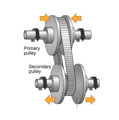
Figure 3 represents the CVT block in the model
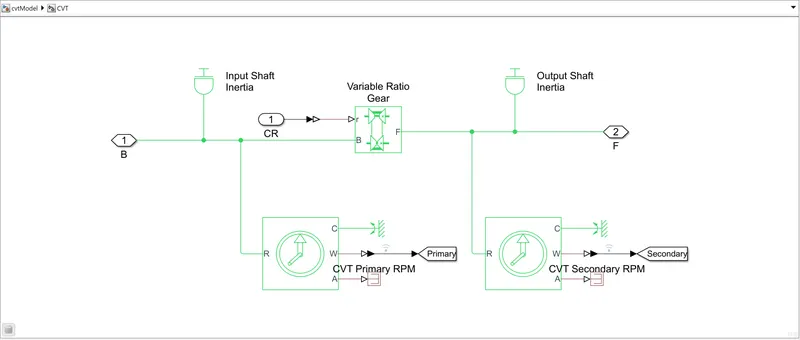
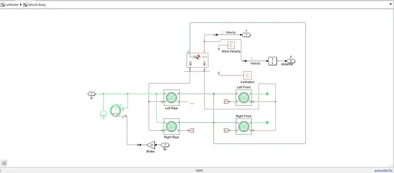
Figure 4 represents the vehicle body block in the model
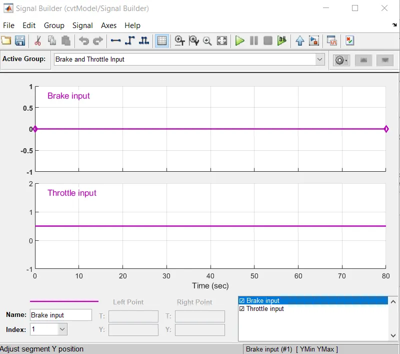
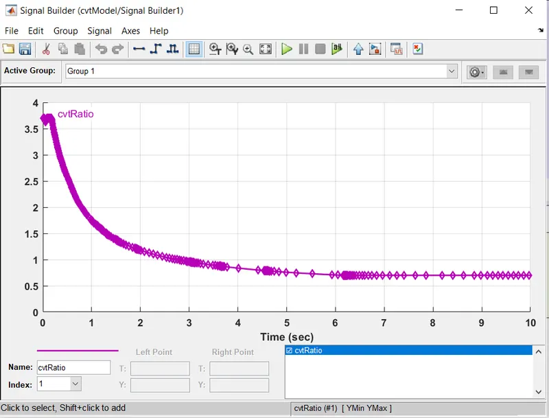
- A signal builder block is used to create signals for brake and throttle. Here brake input is 0 and throttle input is considered as 0.3
- Figure 5 and 6 represent the signal builder blocks representing the brake and throttle input as well as cvt gear ratio input.
On running the simulation , the output obtained in shown in figure 7.As the brake input value is 0, it does not have affect on velocity of the system.
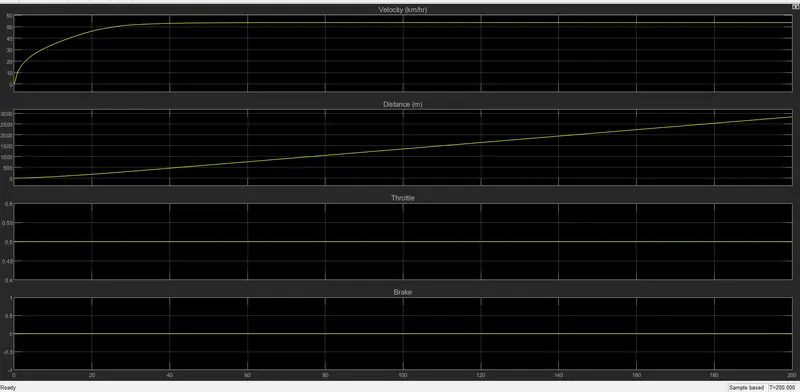
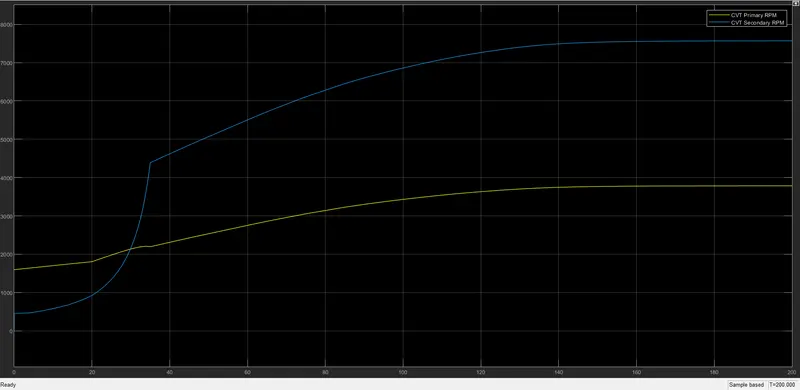
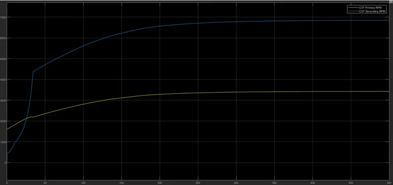
Figure 8 represents the CVT shaft speed. It shows the variation in angular velocities of input and output shaft of variable gear transmission system and these depend on the value of gear ratio.
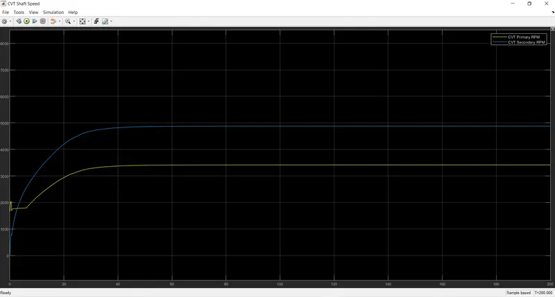
- Here the primary shaft is connected to engine and has a rpm similar to engine rpm considering some losses
- The secondary speed is acheived according to the cvt ratio.
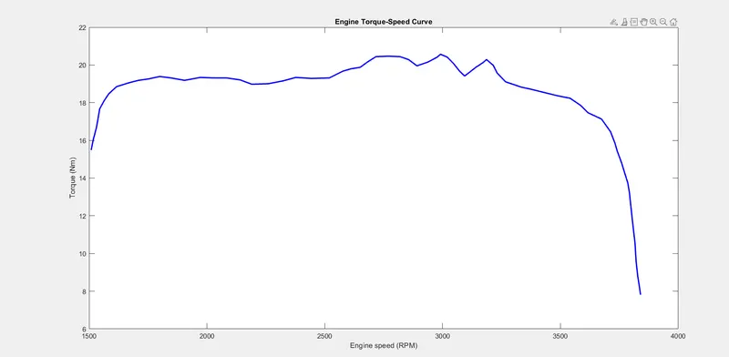
The engine torque speed curve is shown in Figure 9
2)BAJA ATV model- Data Extraction (cvtModel_data)
Figure 10 shows the simulink model of the cvt system with data extraction
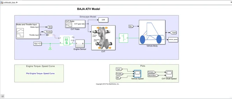
Figure 11 shows the input to the models studied further.
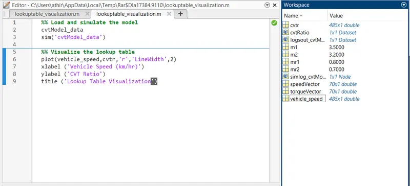
- In this case the variable inputs m1 and m2 are the mass at the input and output shaft in CVT
- Speed vector and torque vectors are the parameters for generic engine.
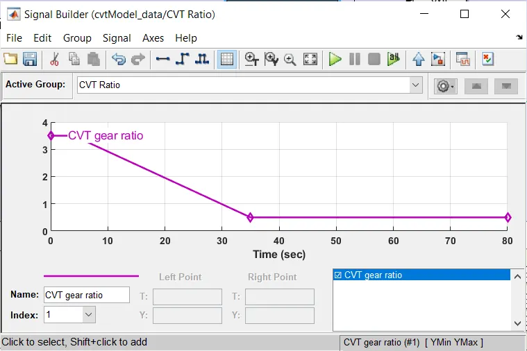
- CVT ratio provided through signal builder varies with time.
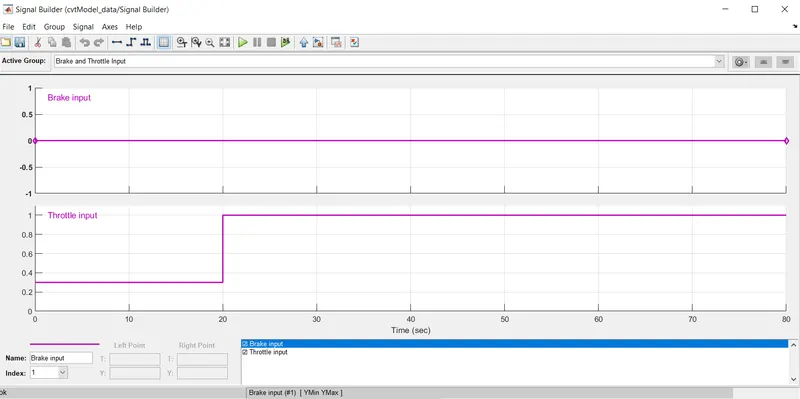
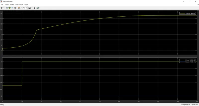
The brake and throttle input is provide through signal builder shown in figure 12, here the throttle input varies from 0.3 upto 20s to 1 after 20s.
The cvt ratio according to the data is shown in figure13.
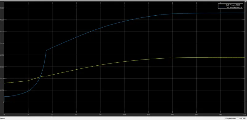
The vehicle speed obtained as output is shown in figure 14 and figure 15 shows the shaft speed of primary and secondary in rpm.
The vehicle speed increases slowly after 60s and reaches a maximum value of 65km/h for a timespan of 200s.
3) BAJA ATV model with dashboard (cvtModel_dashboard)
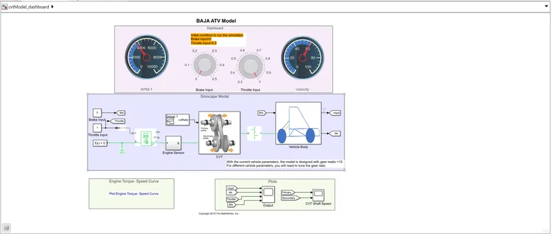
Figure 16 shows the cvt model with dashboard.
- In this model we have a dashboard which contains knobs to control the inputs.
- A knob is provided to control both the parameters in real-time for the user.
- Knob blocks are used to provide input to brake and throttle instead of signal builder and the limits can be set while running the simulation.
Figure 17 shows the cvt gear ratio input
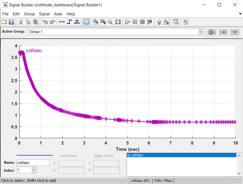
Figure 18 shows the output obtained while simulating the model with dashboard
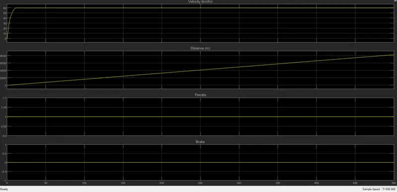
Figure 19 shows the cvt shaft speed obtained
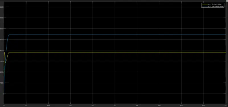
The speed of engine is 3600 rpm and velocity of vehicle is around 65 km/h.
4) BAJA ATV model with cvt ratio rpm (cvtModel_cvtratio_rpm)
Figure 20 shows the simulink model of the system to provide different gear ratios using lookup table
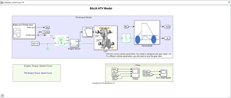
- Here a lookup table is used instead of signal builder to provide different gear ratio data.
- The data in the lookup table is logged to workspace and data is retrived while running the simulation and is provided to cvt subsysytem.
- Figure 21 shows the signal builder input. The throttle input in this sysytem is 1.
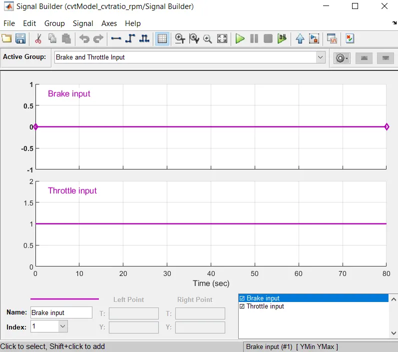
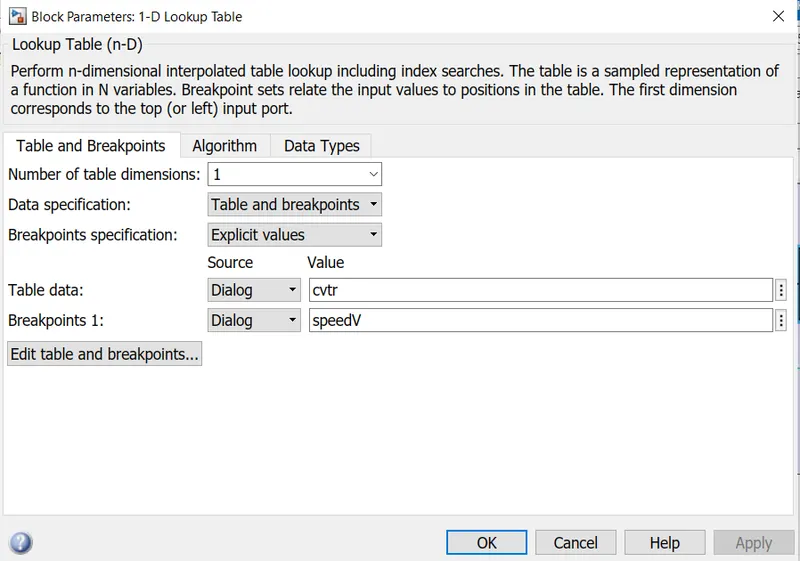
Figure 22 shows the lookup table datas that are logged into workspace.
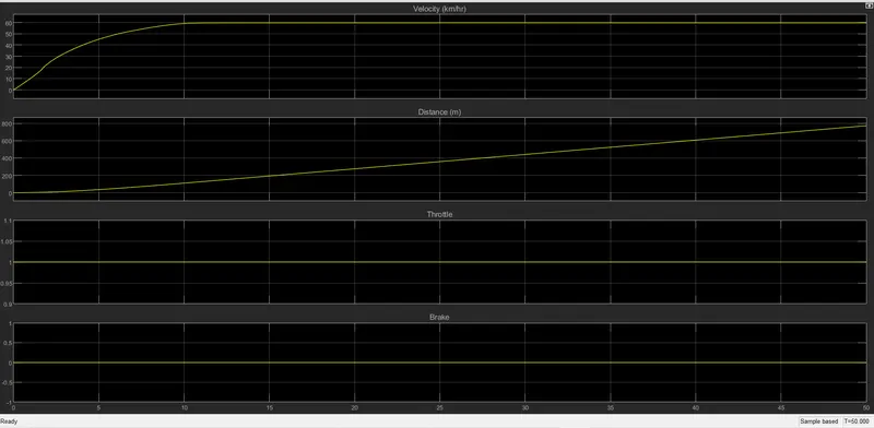
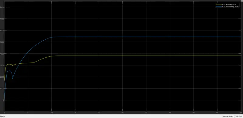
Vehicle speed obtained as output is shown in figure 23 and the cvt shaft speed is represented as waveform in figure 24
5) BAJA ATV model mapped lookup table without dashboard (cvtModel_mapped)
Figure 25 shows the simulink model of model mapped without dashboard. Here both the inputs are provided through constant blocks.
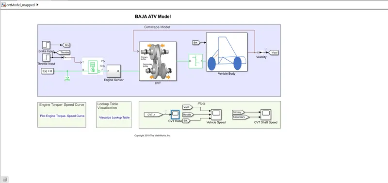
Figure 26 shows the cvt subsytem with lookup table providing different gear ratios
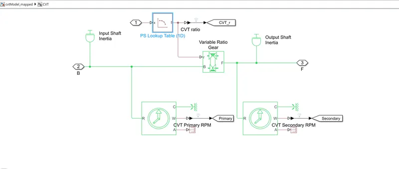
Figure 27 shows the lookup table visualisation and Figure 28 and 29 shows the block parameters of brake input and throttle input
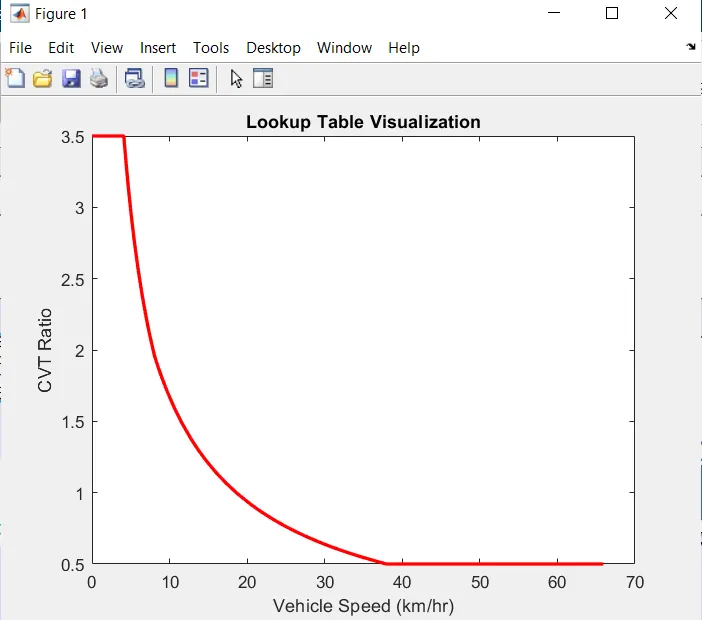
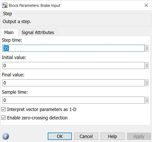
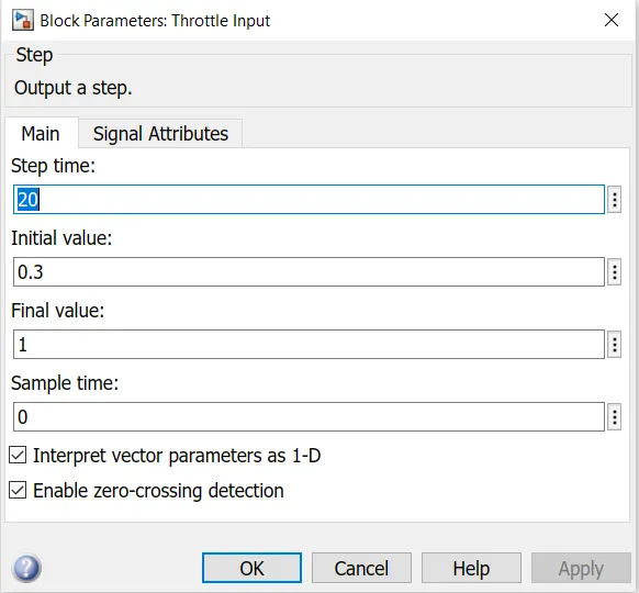
Figure 30 shows the cvt ratio of the system obtained from ps lookup table
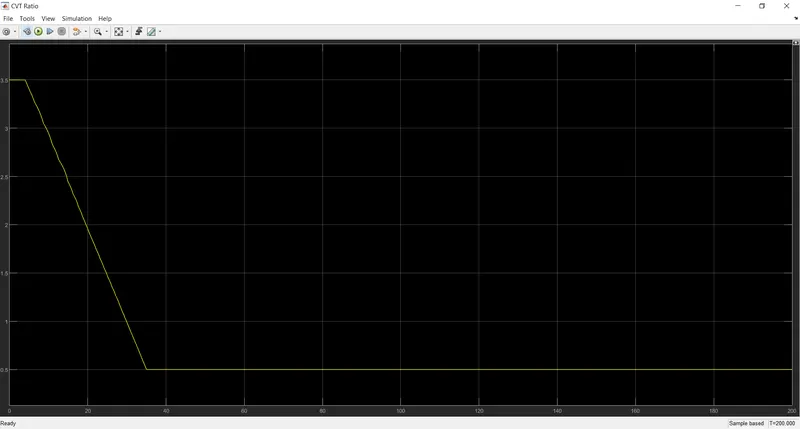
Figure 31 shows the output obtained while running the simulation , here the velocity is more than 60 km/h and the throttle input varies from 0.3 to 1
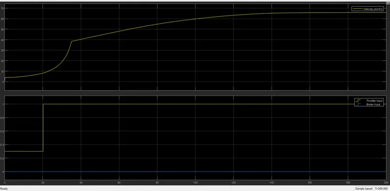
Figure 32 shows the cvt shaft speed obtained during the simulation
6) BAJA ATV model - mapped lookup table with dashboard(cvtModel_dashboard_mapped)
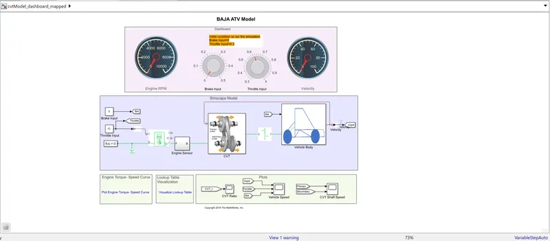
Figure 33 shows the simulink model of the cvt system mapped with dashboard
- Knobs are used to control the input values
- Output velocity is taken as input to PS lookup table
- These data provide variable gear ratios to CVT and corresponding results are obtained during simulation
Figure 34 shows lookup table visualization
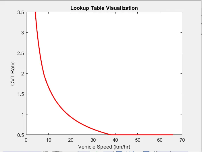
Figure 35 shows the cvt ratio of the model
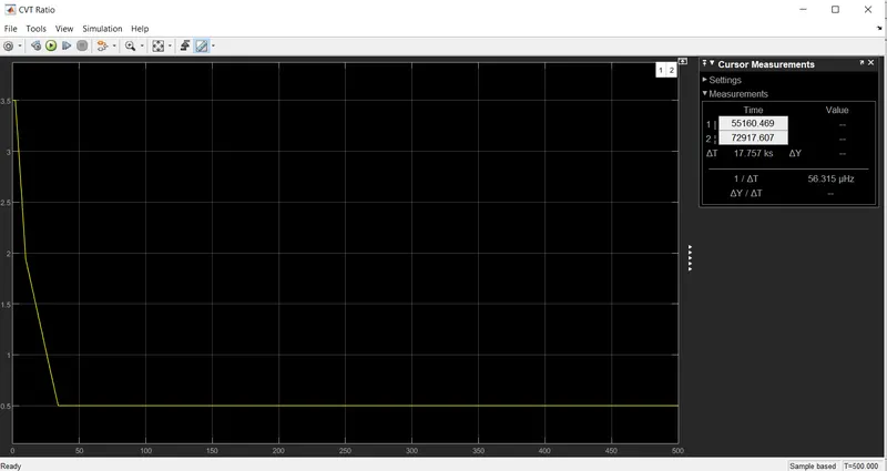
Figure 36 shows the output obtained after simulation, speed of the engine in dashboard is above 3000 rpm ad velocity is above 40km/h and rises to a high value after 100s.
Output velocity is mapped to cvt system.
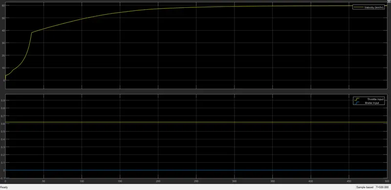
Figure 37 shows the cvt shaft speed obtained
Result
Studied and analyzed BAJA All Terrain Vehicle(ATV) model by carrying out a system level simulation of all terrain vehicle by downloading the models.
- Different BAJA ATV models are studied and the behaviour of cvt system under different input conditions are analysed and understood.
- This model analysis helped to gain knowledge of the vehicle in different conditions.
- Knowledge about performance of braking as well as throttling system is gained through this study.