Project 1 - Interfacing a 16*2 LCD with Arduino using I2C protocol
Project 1 - Interfacing a 16*2 LCD with Arduino using I2C protocol
Aim:
The aim of the project is to demonstrate communication between two Arduinos (one acting as the Master and the other as the Slave) using the I2C communication protocol. The Master Arduino sends a message to the Slave Arduino, which is then displayed on the LCD screen.
This project helps showcase the capability of using I2C as a communication protocol between multiple devices. It also demonstrates how to interface an LCD display with an Arduino and use it to display information received from another Arduino over I2C.
Apparatus required:
- Two Arduino boards (Uno, Nano, or any other compatible Arduino boards)
- 16x2 LCD display with I2C backpack (PCF8574-based module)
- Jumper wires to establish connections between the components
- Breadboard (optional) to make the connections easier
- USB cables to connect the Arduinos to your computer for programming and power
Above apparatus for when the project will be implemented manually, without relying on any online simulation or virtual environment.
Here I'm done this project in TINKERCAD Simulator so here we required
- Two Arduino boards (Uno, Nano, or any other compatible Arduino boards)
- 16x2 LCD display with I2C backpack (PCF8574-based module)
Description:
This project focuses on interfacing an Arduino Uno with a PCF8574 module and a 16x2 LCD display using the I2C communication protocol. The aim is to send messages from the Arduino to the LCD display and showcase the communication between the components.
The Arduino Uno acts as the master device, while the PCF8574 module serves as an I/O expander, allowing the Arduino to control the LCD display with minimal pins. The PCF8574 module provides additional digital input/output pins through the I2C protocol.
The project involves the following steps:
Hardware Setup:
Connect the Arduino Uno to the PCF8574 module using the SDA (data) and SCL (clock) lines for I2C communication.
Connect the PCF8574 module to the 16x2 LCD display, wiring the appropriate pins for data, control, and power.
Software Implementation:
Write the code for the Arduino Uno to send messages to be displayed on the LCD screen.
Utilize the Wire library to establish I2C communication between the Arduino and the PCF8574 module.
Configure the PCF8574 module to control the LCD display by sending the necessary commands and data.
Message Display:
The Arduino Uno sends messages to the PCF8574 module via I2C.
The PCF8574 module receives the messages and controls the LCD display accordingly.
The LCD display shows the received messages in real-time.
By completing this project, you will gain a better understanding of I2C communication, learn how to interface the PCF8574 module with an Arduino Uno, and successfully display messages on a 16x2 LCD display. This project can serve as a foundation for more complex projects involving I2C-based communication and peripheral control.
Arduino UNO:
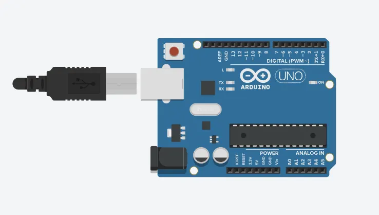
An Arduino is actually a microcontroller based kit which can be either used directly by purchasing from the vendor or can be made at home using the components, owing to its open source hardware feature. It is basically used in communications and in controlling or operating many devices. It was founded by Massimo Banzi and David Cuartielles in 2005.
Arduino Architecture:
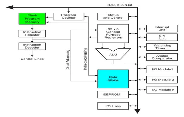
Arduino’s processor basically uses the Harvard architecture where the program code and program data have separate memory. It consists of two memories- Program memory and the data memory.The code is stored in the flash program memory, whereas the data is stored in the data memory. The Atmega328 has 32 KB of flash memory for storing code (of which 0.5 KB is used for the bootloader), 2 KB of SRAM and 1 KB of EEPROM and operates with a clock speed of 16MHz.
Arduino Pin Diagram:
A typical example of Arduino board is Arduino Uno. It consists of ATmega328- a 28 pin microcontroller.
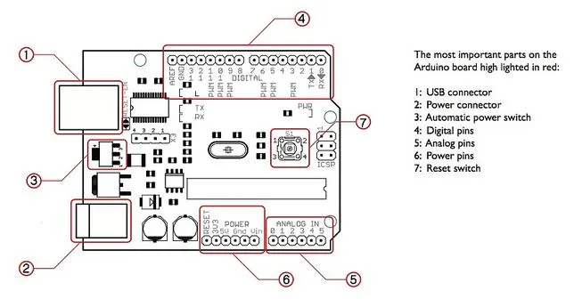
Arduino Uno consists of 14 digital input/output pins (of which 6 can be used as PWM outputs), 6 analog inputs, a 16 MHz crystal oscillator, a USB connection, a power jack, an ICSP header, and a reset button
Power Jack: Arduino can be power either from the pc through a USB or through external source like adaptor or a battery. It can operate on a external supply of 7 to 12V. Power can be applied externally through the pin Vin or by giving voltage reference through the IORef pin.
Digital Inputs: It consists of 14 digital inputs/output pins, each of which provide or take up 40mA current. Some of them have special functions like pins 0 and 1, which act as Rx and Tx respectively , for serial communication, pins 2 and 3-which are external interrupts, pins 3,5,6,9,11 which provides pwm output and pin 13 where LED is connected.
Analog inputs: It has 6 analog input/output pins, each providing a resolution of 10 bits.
ARef: It provides reference to the analog inputs
Reset: It resets the microcontroller when low.
How to program an Arduino?
The most important advantage with Arduino is the programs can be directly loaded to the device without requiring any hardware programmer to burn the program. This is done because of the presence of the 0.5KB of Bootloader which allows the program to be burned into the circuit. All we have to do is to download the Arduino software and writing the code.
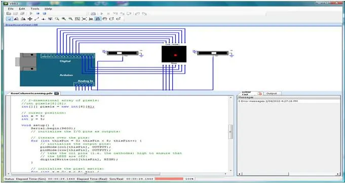
The Arduino tool window consists of the toolbar with the buttons like verify, upload, new, open, save, serial monitor. It also consists of a text editor to write the code, a message area which displays the feedback like showing the errors, the text console which displays the output and a series of menus like the File, Edit, Tools menu.
Steps to program an Arduino
Programs written in Arduino are known as sketches. A basic sketch consists of 3 parts
1. Declaration of Variables
2. Initialization: It is written in the setup () function.
3. Control code: It is written in the loop () function.
- The sketch is saved with .ino extension. Any operations like verifying, opening a sketch, saving a sketch can be done using the buttons on the toolbar or using the tool menu.
- The sketch should be stored in the sketchbook directory.
- Chose the proper board from the tools menu and the serial port numbers.
- Click on the upload button or chose upload from the tools menu. Thus the code is uploaded by the bootloader onto the microcontroller.
Few of basic Adruino functions are:
- Microcontroller: The Arduino Uno is powered by the ATmega328P microcontroller running at 16 MHz.
- Digital I/O Pins: It has a total of 14 digital input/output pins, with 6 of them capable of providing PWM (Pulse Width Modulation) output.
- Analog Inputs: The board has 6 analog input pins, marked as A0 to A5, which can also be used as digital I/O pins.
- Memory: The ATmega328P microcontroller on the Uno has 32KB of flash memory for storing the program, 2KB of SRAM, and 1KB of EEPROM.
- Communication: The Uno has a USB interface for connecting to a computer, allowing easy programming and serial communication. It also has a dedicated ICSP (In-Circuit Serial Programming) header for advanced programming and debugging.
- Power Supply: The board can be powered either through the USB connection or an external power supply. The recommended operating voltage is 5V.
- Compatibility: The Arduino Uno is compatible with a wide range of shields, which are expansion boards that provide additional functionality such as Wi-Fi, Bluetooth, motor control, and more.
- Programming: The Uno is programmed using the Arduino programming language (based on C/C++) and the Arduino IDE (Integrated Development Environment), which provides a simple and beginner-friendly interface for writing and uploading code.
PCF8574 Module:
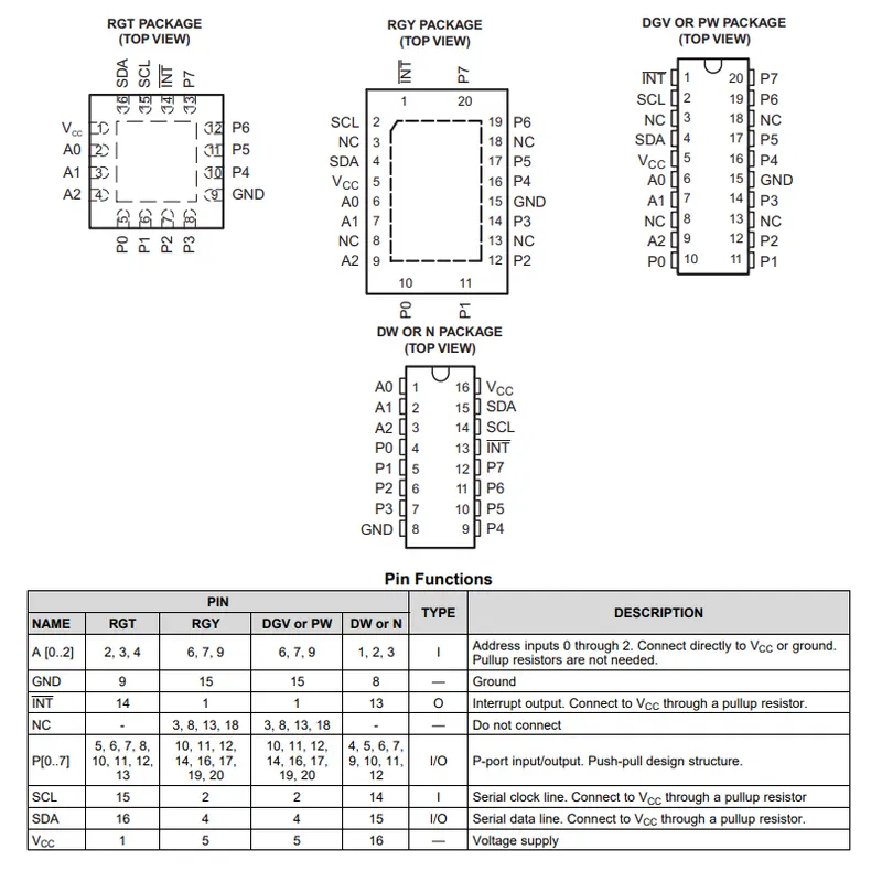
This 8-bit input/output (I/O) expander for the two-line bidirectional bus (I2C) is designed for 2.5-V to 6-V VCC operation.
The PCF8574 device provides general-purpose remote I/O expansion for most microcontroller families by way of the I2C interface [serial clock (SCL), serial data (SDA)]. The device features an 8-bit quasi-bidirectional I/O port (P0–P7), including latched outputs with high current drive capability for directly driving LEDs. Each quasi-bidirectional I/O can be used as an input or output without the use of a data-direction control signal. At power on, the I/Os are high. In this mode, only a current source to VCC is active.
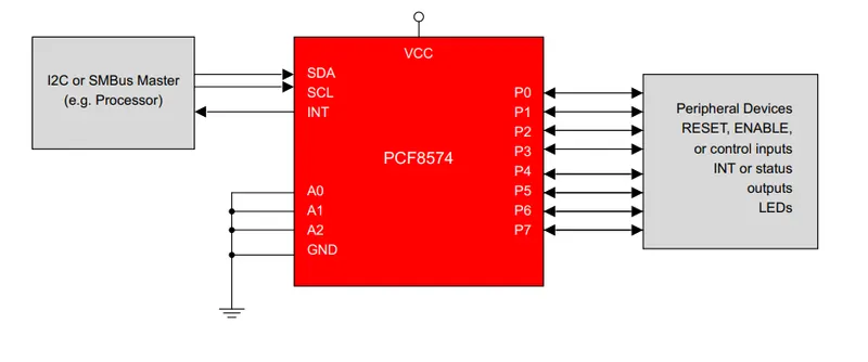
The PCF8574 is an I/O expander module commonly used for expanding the input/output capabilities of microcontrollers, such as Arduino. It provides additional digital input/output pins using only two communication lines (SDA and SCL) through the I2C (Inter-Integrated Circuit) protocol.
Here are some key features and specifications of the PCF8574 module:
I/O Expansion: The PCF8574 module offers 8 additional digital input/output (I/O) pins, which can be individually configured as either input or output.
I2C Communication: The module communicates with the microcontroller using the I2C serial communication protocol. It acts as a slave device on the I2C bus.
Addressing: The PCF8574 module has three address selection pins (A0, A1, and A2) that allow you to set its unique I2C address. This feature enables the use of multiple PCF8574 modules in the same project without address conflicts.
5V Operation: The module typically operates at 5V, making it compatible with most microcontrollers that use 5V logic levels. However, some variants of the PCF8574 module, such as the PCF8574A, support operation at both 3.3V and 5V.
Input/Output Logic: The PCF8574 module uses open-drain outputs, meaning the outputs can only pull the signals low but cannot drive them high. To read a logical high, you need to enable the internal pull-up resistors or use an external pull-up resistor.
Cascading: Multiple PCF8574 modules can be cascaded together to provide even more digital I/O pins. Each module requires a unique I2C address using the address selection pins.
The PCF8574 module is widely used in various applications where additional digital I/O pins are required, such as controlling multiple sensors, interfacing with LCD displays, driving relays, and more. It offers a convenient and efficient way to expand the capabilities of microcontrollers using the I2C bus, reducing the number of required pins and simplifying the wiring.
I2C LCD Display
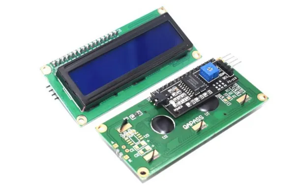
This is I2C interface 16x2 LCD display module, a high-quality 2 line 16 character LCD module with on-board contrast control adjustment, backlight and I2C communication interface. For Arduino beginners, no more cumbersome and complex LCD driver circuit connection. The real significance advantages of this I2C Serial LCD module will simplify the circuit connection, save some I/O pins on Arduino board, simplified firmware development with widely available Arduino library.
Brief Data:
- Compatible with Arduino Board or other controller board with I2C bus.
- Display Type: Negative white on Blue backlight.
- I2C Address:0x38-0x3F (0x3F default)
- Supply voltage: 5V
- Interface: I2C to 4bits LCD data and control lines.
- Contrast Adjustment: built-in Potentiometer.
- Backlight Control: Firmware or jumper wire.
- Board Size: 80x36 mm
Setting Up:
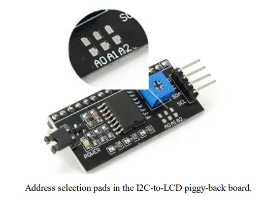
Hitachi’s HD44780 based character LCD are very cheap and widely available, and is an essential part for any project that displays information. Using the LCD piggy-back board, desired data can be displayed on the LCD through the I2C bus. In principle, such backpacks are built around PCF8574 (from NXP) which is a general purpose bidirectional 8 bit I/O port expander that uses the I2C protocol. The PCF8574 is a silicon CMOS circuit provides general purpose remote I/O expansion (an 8-bit quasi-bidirectional) for most microcontroller families via the two-line bidirectional bus (I2C-bus). Note that most piggy-back modules are centered around PCF8574T (SO16 package of PCF8574 in DIP16 package) with a default slave address of 0x27. If your piggy-back board holds a PCF8574AT chip, then the default slave address will change to 0x3F. In short, if the piggy-back board is based on PCF8574T and the address connections (A0-A1-A2) are not bridged with solder it will have the slave address 0x27.
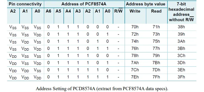
Note: When the pad A0~A2 is open, the pin is pull up to VDD. When the pin is solder shorted, it is pull down to VSS.
The default setting of this module is A0~A2 all open, so is pull up to VDD. The address is 3Fh in this case.
Reference circuit diagram of an Arduino-compatible LCD backpack is shown below. What follows next is information on how to use one of these inexpensive backpacks to interface with a microcontroller in ways it was exactly intended
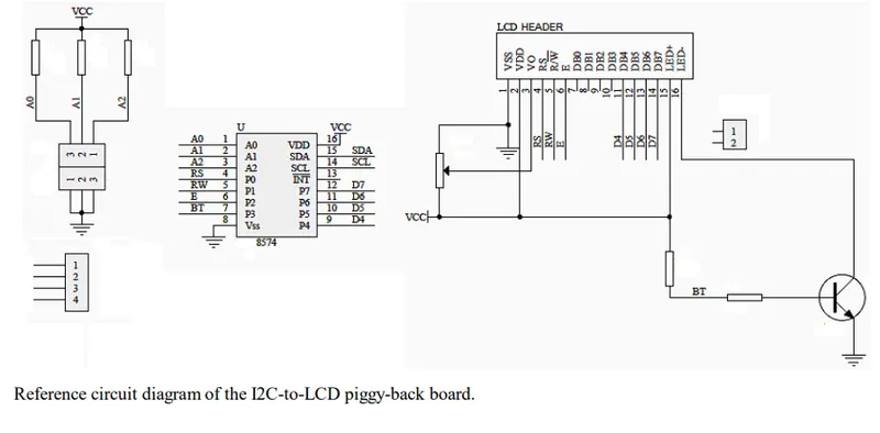
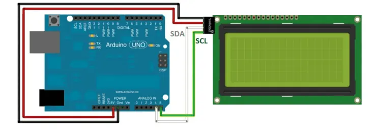
At first you need to solder the I2C-to-LCD piggy-back board to the 16-pins LCD module. Ensure that the I2C-to-LCD piggy-back board pins are straight and fit in the LCD module, then solder in the first pin while keeping the I2C-to LCD piggy-back board in the same plane with the LCD module. Once you have finished the soldering work, get four jumper wires and connect the LCD module to your Arduino as per the instruction given below.
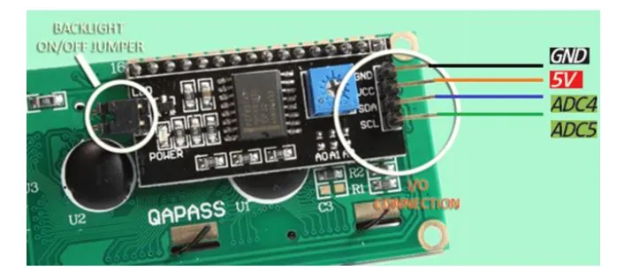
LCD display to Arduino wiring.
Code:
code for both the Master and Slave Arduinos to send a message to the LCD display using I2C communication:
Master Arduino (Sender):
//Preprocessor Library selection
#include <Wire.h>

/* Global Section */

void setup() {
  Wire.begin(); // Start I2C communication
}

/* Sub function definition */

void loop() {
  // Send a message to the Slave Arduino
  Wire.beginTransmission(0x27); // PCF8574 module address (change if needed)
  Wire.write("Hello from Master"); // Message to be sent
  Wire.endTransmission();
  delay(1000); // Delay between messages
}
Slave Arduino (Receiver):
// Prerocessor Library selection
#include <Wire.h>
#include <LiquidCrystal_I2C.h>

// Global section

LiquidCrystal_I2C lcd(0x27, 16, 2); // PCF8574 module address, LCD columns, LCD rows (change if needed)

void setup() {
  Wire.begin(9); // Set Slave Arduino address (change if needed)
  Wire.onReceive(receiveEvent); // Register the receive event
  lcd.begin(16, 2); // Initialize the LCD
  lcd.backlight(); // Turn on the LCD backlight
  lcd.setCursor(0, 0);
  lcd.print("Slave Arduino");
}

void loop() {
  // Slave Arduino loop code
}

void receiveEvent(int byteCount) {
  String receivedMessage = "";

  while (Wire.available()) {
    char c = Wire.read();
    receivedMessage += c;
  }

  lcd.clear();
  lcd.setCursor(0, 0);
  lcd.print(receivedMessage);
}
Result:
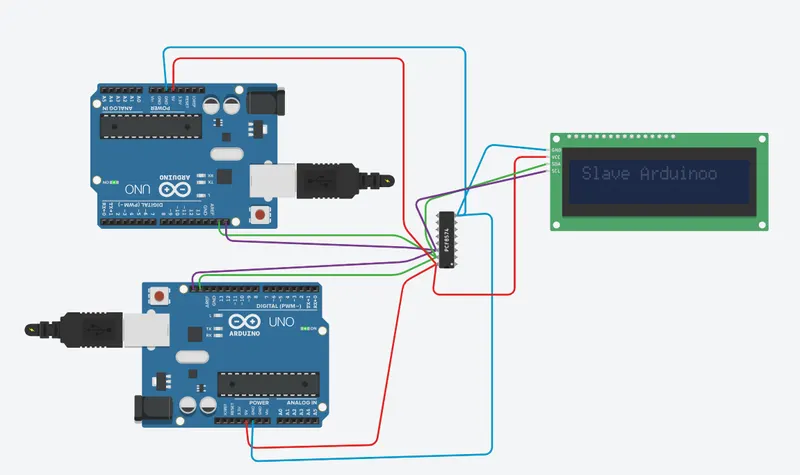
As a result of this project, you will obtain a working system where the Arduino Uno communicates with the PCF8574 module and controls a 16x2 LCD display. The messages sent from the Arduino Uno will be displayed on the LCD screen in real-time.
The key outcomes of this project include:
Successful interfacing: You will have successfully established communication between the Arduino Uno and the PCF8574 module using the I2C protocol. This demonstrates your ability to connect and communicate with external devices.
Expanded I/O capabilities: The PCF8574 module acts as an I/O expander, providing additional digital input/output pins to the Arduino Uno. This allows you to control the 16x2 LCD display without using a large number of pins directly on the Arduino.
Real-time message display: The messages sent from the Arduino Uno will be displayed on the LCD screen connected to the PCF8574 module. This demonstrates your ability to send data and control an output device.
Understanding of I2C communication: Through this project, you will gain a deeper understanding of the I2C communication protocol and its implementation. You will learn how to configure the I2C communication between the Arduino Uno and the PCF8574 module.
Overall, the project provides hands-on experience in interfacing devices, utilizing an I/O expander, and displaying information on an LCD screen. It also enhances your understanding of I2C communication and expands your knowledge of working with Arduino-based projects.