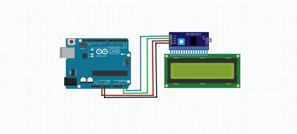
Project 1 - Interfacing a 16*2 LCD with Arduino using I2C protocol
1.
Interfacing a 16*2 LCD with Arduino using I2C protocol.
Program:
#include <Wire.h>
#include <LiquidCrystal_I2C.h>
//I2C pins declaration
LiquidCrystal_I2C lcd(0x27, 2, 1, 0, 4, 5, 6, 7, 3, POSITIVE);

void setup()
{

lcd.begin(16,2);//Defining 16 columns and 2 rows of lcd display
lcd.backlight();//To Power ON the back light
//lcd.backlight();// To Power OFF the back light

}

void loop()
{
//Write your code
lcd.setCursor(0,0); //Defining positon to write from first row,first column .
lcd.print(" Tech Maker "); //You can write 16 Characters per line .
delay(1000);//Delay used to give a dynamic effect
lcd.setCursor(0,1);  //Defining positon to write from second row,first column .
delay(8000);

lcd.clear();//Clean the screen
lcd.setCursor(0,0);
lcd.print("HI");
lcd.setCursor(0,1);
lcd.print("SKILL-LYNC");
delay(8000);
}
I2C:
Each I2C bus consists of two signals: SCL and SDA. SCL is the clock signal, and SDA is the data signal. The clock signal is always generated by the current bus master; some slave devices may force the clock low at times to delay the master sending more data (or to require more time to prepare data before the master attempts to clock it out). This is called “clock stretching” and is described on the protocol page.
Simulation: