Project 1 - Interfacing a 16*2 LCD with Arduino using I2C protocol
Objectives:
- To execute Master to slave communication, data transmission by using I2C protocol.
- Display the transmitted data in a 16x2 LCD using I2C protocol.
I2C LCD Interfacing:
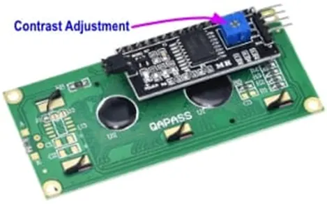
The LCD is ideal for displaying text and numbers and special characters. LCDs incorporate a small add-on circuit (backpack) mounted on the back of the LCD module. The module features a controller chip handling I2C communications and an adjustable potentiometer for changing the intensity of the LED backlight. An I2C LCD advantage is that wiring is straightforward, requiring only two data pins to control the LCD.
A standard LCD requires over ten connections, which can be a problem if your Arduino does not have many GPIO pins available. If you happen to have an LCD without an I2C interface incorporated into the design, these can be easily acquired separately.
The LCD displays each character through a matrix grid of 5×8 pixels. These pixels can display standard text, numbers, or special characters and can also be programmed to display custom characters easily.
Connection for the I2C LCD to Arduino UNO
Connecting the Arduino UNO to the I2C interface of the LCD requires only four connections. The connections include two for power and two for data. The chart below shows the connections needed.
|
I2C LCDPin |
Arduino UNOPin |
|
GND |
GND |
|
VCC |
5V |
|
SDA |
A4(SDA) |
|
SCL |
A5(SCL) |
The I2C protocol involves using two lines to send and receive data: a serial clock pin (SCL) that the Arduino Controller board pulses at a regular interval, and a serial data pin (SDA) over which data is sent between the two devices. As the clock line changes from low to high (known as the rising edge of the clock pulse), a single bit of information - that will form in sequence the address of a specific device and a command or data - is transferred from the board to the I2C device over the SDA line. When this information is sent - bit after bit -, the called upon device executes the request and transmits it's data back - if required - to the board over the same line using the clock signal still generated by the Controller on SCL as timing.
Because the I2C protocol allows for each enabled device to have it's own unique address, and as both controller and peripheral devices to take turns communicating over a single line, it is possible for your Arduino board to communicate (in turn) with many devices, or other boards, while using just two pins of your microcontroller.
Arduino Family Pinouts
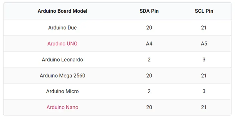
The I2C LCD interface is compatible across much of the Arduino family. The pin functions remain the same, but the labeling of those pins might be different.
This chart will assist in identifying the pins on your Arduino model to the SDA and SCL functions.
The Arduino R3 also extends the Data Line (SDA) and Clock Line (SCL) to the header pin beside the AREF header.
Contrast Adjust – I2C LCD Display
I2C LCD Controller Contrast Adjustment Once we have to connect the four connections to LCD, which will provide power to the LCD. The LCD has an adjustment on it which needs to be approximately set for back light to allow to see characters on the display.
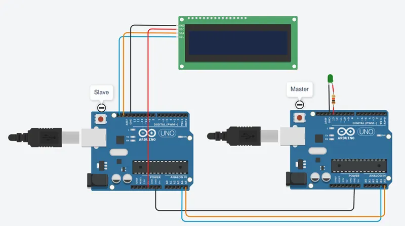
Required Hardware’s
- Arduino uno bords -2
- 16x2 I2C LCD -1
- Connection wires.
Circuit Hardware Connections:
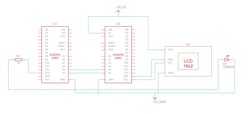
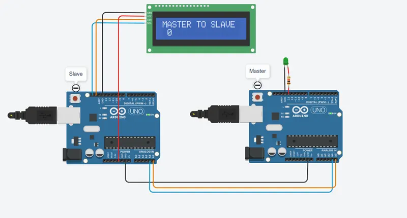
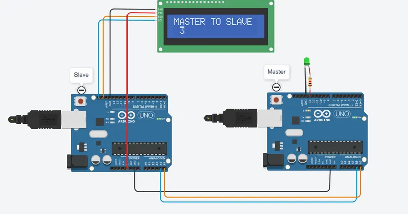
- Two ARDUINO boards master and slave are connected by I2C pins A4 and A5 parallel.
- The 16x2 I2C LCD was connected to slave through the I2C protocol pins SDA and SCL pins.
- The LCD gets supply from ARDUINO board 5V and GND pins.
Schematic Diagram:
Program :
Master Arduino :
// Master Program
#include //i2c library header file
int x = 0;
int LED_pin =13;
byte y=0;
void setup()
{
pinMode(LED_pin,OUTPUT); //Internal LED Pin as output
Serial.begin(9600); //Enable Serial Print
Wire.begin(8); // Start the I2C Bus as Master address is 8
}
void loop()
{
Wire.beginTransmission(9); // transmit to device 9
Wire.write(x); // The value of x write on i2c bus
Wire.endTransmission(); // stop the transmitting
x++; // Increment x value
if (x > 10) x = 0; // Reset x once it reached 10
Serial.println(x); // Print x in serial monitor for verification
digitalWrite (LED_pin, HIGH); //Set LED ON
delay(500); //LED ON delay
digitalWrite (LED_pin, LOW); //Set LED OFF
delay(500); //LED OFF Delay
//delay(1000); // Delay for Transmission
}
Slave Arduino :
//Slave program
#include //i2c LCD header file
#include //i2c communication header file
Adafruit_LiquidCrystal lcd(0); //i2c LCD initialize
byte x=0;
void setup()
{
Serial.begin(9600); //Serial Monitor initialize
lcd.begin(16, 2); // ON the LCD Display
Wire.begin(9); //i2c start with address 9
Wire.onReceive(receive); //Data recive function call
}
void receive(int bytes) //Recive function
{
x = Wire.read(); // read one character from the I2C
Serial.print(x); // Print the recived data on serial monitor
}
void loop()
{
lcd.setCursor(1,0); //LCD cursor set
lcd.clear(); // Clear the LCD
lcd.print("MASTER TO SLAVE"); //To print the heading
lcd.setCursor(1,1); //set cursor for data printing
lcd.print(x); //Print the recived data
delay(1000); //Delay for next data
}
Program function:
There are two programs; one is for ARDUINO Master Board, Another one for ARDUINO Slave board. The Master program is constructed to transmit number from 1 to 10 to Slave program, same time the Green LED will blink during the data transmission, the executions of the program ware commented on every line of the each programs.
The Slave program was constructed to get the data from Master and display the data on 16x2 I2C LCD, The LCD is connected only four wires VCC, GND, SDA, SCL
The Output:
Conclusion:
The project of I2C protocol communication from Master to slave was developed and executed with two ARDUINO boards Master, Slave and one I2C LCD display.