Project 1 - Interfacing a 16*2 LCD with Arduino using I2C protocol
# Solution:-
Overview of this Project:-
In this project I am implementing the Code for “Interfacing a 16*2 LCD with two ARDUINO (one for Master and other one for Slave) using Inter-Integrated Circuit (I2C) communication protocol” by sending the message to LCD using I2C communication protocol and display the message on LCD screen.
Goals:
- Communication between Arduino and 16*2 LCD using I2C protocol.
- Displaying the message sent by Master and received by slave i.e. LCD display.
Key Highlights of the Project:
- Using the inter-integrated circuit communication protocol, transferring the data i.e. the message we want to display is sent to the LCD.
- Two Arduino’s connected to the LCD display and the communication is executed using I2C protocol between Arduino and the LDC display.
Deliverables of this project:
- Communication between the Arduino’s and LCD using I2C.
- The message passed from master to slave and displayed on the 16*2 LCD.
Expected Outcomes:
- Here we get the Knowledge of I2C interfacing with the Arduino.
- The Hardware connection of all components used in this project.
- Displaying the message sent by master (Arduino) and received by the slave (16*2 LCD display).
Objective: -
To send a message from slave to master using Inter-Integrated Circuit (I2C) communication protocol in Arduino and displaying the message on 16*2 LCD screen.
THEORY:-
Several functions of Arduino's Wire Library are used to accomplish this. Arduino 1, the Master, is programmed to request, and then read, 8 bytes of data sent from the uniquely addressed Slave Arduino. Once that message is received, it can then be viewed in the Tinkercad serial monitor window.
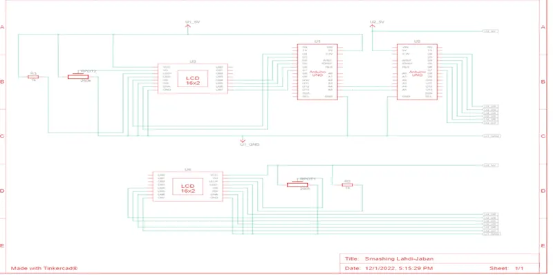
The analog pins A4 and A5 in Arduino are used for I2C communication. Here the digital pin 2 is connected to RS of LCD. Digital pin 3 connected to E of LCD. The Digital pins 4, 5, 6, 7 are connected to DB1, DB2, DB3, DB4 of LCD. Input supply 5v and ground are connected to the LCD from Arduino. The potentiometer is used to turn ON and OFF the LCD.
- A serial clock pin (SCL) that the Arduino Master board pulses at a regular interval
- A serial data pin (SDA) over which data is sent between the two devices.
A single bit of information - that will form in sequence the address of a specific device and a command or data - is transferred from the board to the I2C device over the SDA line. When this information is sent - bit after bit -, the called upon device executes the request and transmits it's data back - if required - to the board over the same line using the clock signal still generated by the Master on SCL as timing. it is possible for your Arduino board to communicate (in turn) with many devices, or other boards, while using just two pins of your microcontroller.
Materials Required:-
- ARDUINO UNO Board-2
- LCD(16x2)-2
- Bread board-2
- Potentiometer-2
- Resistor-2
- Connecting wires
Software Used: - TINKERCAD
Circuit Implementation:-
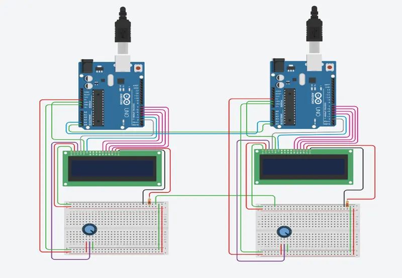
Schematic Diagram:-
Code Implementation:-
// Master Code
#include <Wire.h>           // Including I2C protocol header file
#include <LiquidCrystal.h>	// Including Lcd function header file
LiquidCrystal lcd(2,3,4,5,6,7);// Lcd Pins are defined
char MasterReceive[16];	// variable defined to receive the message
void setup()
{
  Serial.begin(9600);	// Initialize the serial Monitor
  Wire.begin();			// initialize the I2c protocol
  lcd.begin(16,2);		// initialize the Lcd
  lcd.clear();			// Clearing the Lcd display
}
void loop()				// Loop function is defined
{
  // requesting the address and character(data) from peripheral
  Wire.requestFrom(8,16);
  lcd.setCursor(0,0);//Setting cursor position to starting 0,0
  lcd.print("Master");// printing the message on Lcd
  lcd.setCursor(0,1);// Again setting the cursor position to 0,1
  int i=0;		// int type variable i is defined and initialize
  while(0<Wire.available())// Check the no of bytes available
  {
    MasterReceive[i]=Wire.read();//receiving the byte as character
    i++;			// incrementing the counter
  }
  lcd.print(MasterReceive);// printing the received message
  delay(1000);	// providing the delay of 1 sec
  Wire.end();	// Ending the I2C Transmission
}
// Slave Code
#include <Wire.h>           // Including I2C protocol header file
#include <LiquidCrystal.h>	// Including Lcd function header file
LiquidCrystal lcd(2,3,4,5,6,7);// Lcd Pins are defined
void setup()
{
  Serial.begin(9600);	// Initialize the serial Monitor
  Wire.begin(8);			// initialize the I2c protocol
  Wire.onRequest(send);// call the send function to request bute
  lcd.begin(16,2);		// initialize the Lcd
  lcd.clear();			// Clearing the Lcd display
}
void loop()				// loop function started
{
  lcd.setCursor(0,0);//Setting cursor position to starting 0,0
  lcd.print("Slave");// printing the message on Lcd
  lcd.setCursor(0,1);// Again setting the cursor position to 0,1
  lcd.println("Msg sent2 Master");//Displaying the message in Lcd
}
void send()
{
	char ch[17]="Hi Ramlochan ";//creating string
	Wire.write(ch);              //To send message to Master
}
Output:-
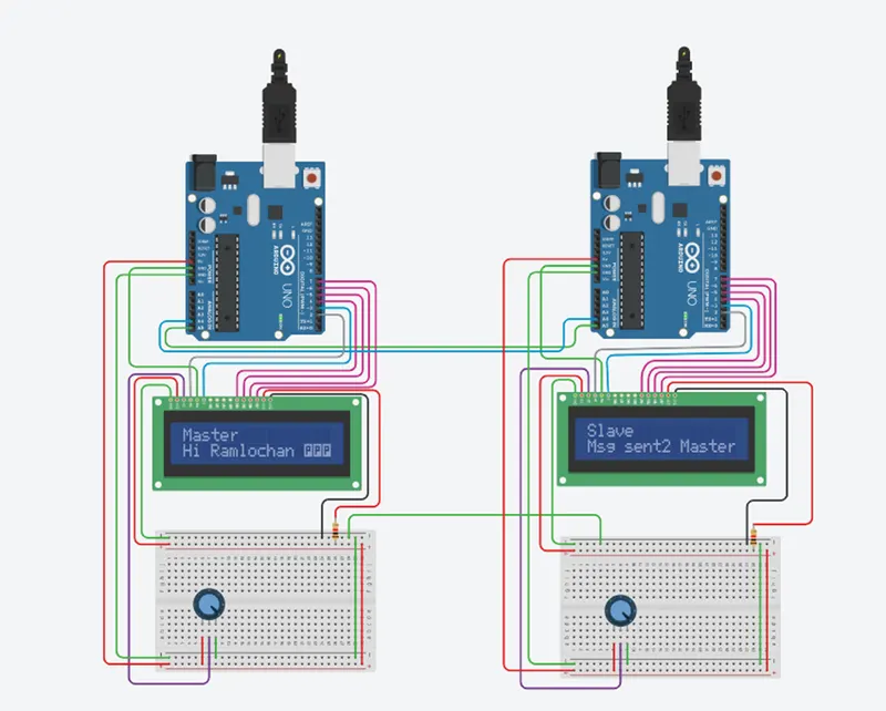
Conclusion:-
The message sent from slave is received by master and displayed in 16*2 LCD. The communication between the master and slave Arduino was implemented using I2C protocol.