Project 1 _Creating an Architectural plan for the provided plot size and develop relevant basic structural drawings
AIM & ITRODUCTION :
AIM :
- To draft and design a layout of a residential building as architectural and structural drawing with the plot size of 60'x20' (18.3m x 6m) in autocad.
INTRODUCTION:
- The Architectural drawing contains the Floor plan, Elevation and the Sections of the building.
- The Floor plan of the buiding has the area inside the building like rooms, kitchen, toilets and other details such as doors, windows, steps etc.
- The Elevation of the building is a front view of the buiding.
- The Sections are the cross section of the buiding which we want to the cross sectional view of the inner building.
- The Structural drawing contains the Column details, Beam details and footing details of the building.
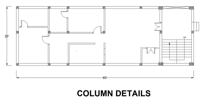
- The Column details shows the number of columns are needed for the building to build and it can be seen in the intersections of the walls or beams.
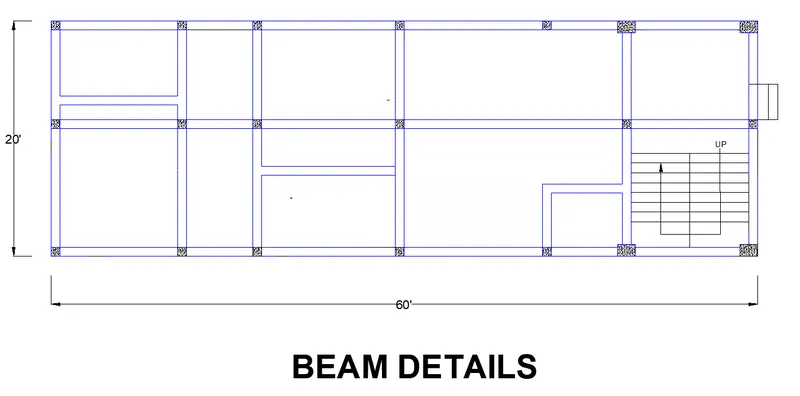
- The Beam details shows where the beams are needs to be provided and it is provided by connecting all the columns.
- The Footing details shows the presents of footings under the colums and also it shows the size of the excavation needs to be done around the column.
PROCEDURE :
A. ) ARCHITECTURAL DRAWING :
1. Floor Plan :
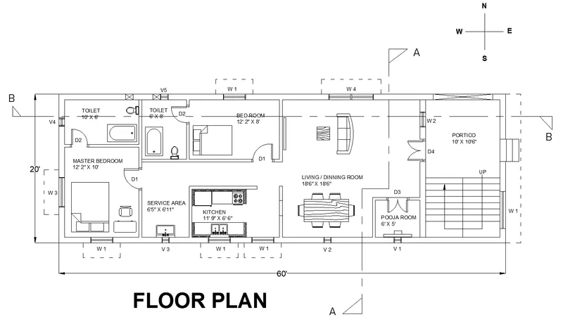
- To create a floor plan the dimensions of the total area must be created through the rectangle tool as area=60'x20'.
- Then the width of the wall should be done as 9" by using offset tool.
- After that the rooms, kitchen, toilets are needs to be separated inside the plan with the partition wall inbetween them as width of 4.5" by using the offset tool.
- The doors are then needs to be attached for every area separated for access into it, the entrance distance should be 3' or more for various purposes required.
- Likewise the windows, ventilators, and exhaust fan are also needs to be attached as per the required size and positions.
- The staircase is provided with a tread size = 10" and the riser size = 7".
- Atlast should use save the created draft with shortkey "crtl+s" or by the command "qsave".
2. Elevation :
- To create a Elevation fom the floor plan, the construction line was used with tool name "xline" to extrat a exact size of the building walls, doors and the window size.
- In the elevation view the O.H.T can be seen as a height of 6' from the top the parapet wall and the sunshades are can be seen at the height of 7' from the plinth level.
- Before that, the G.L , Plinth level, lintel level and the roof level has to be predefined as required height using the "offset" tool.
- Then the excess lines needs to be trimmed using the "trim" tool.
- Likewise using the xline tool and the trim tool all the other parts are to be created such as staircase.
- Atlast should use save the created draft with shortkey "crtl+s" or by the command "qsave".
3. Sections :
- To create a section or cross sectional view of the separated part of the floor plan with sectional line the" Xline " tool .
- The "xline" tool is used to get the exact size of the walls, windows and doors of the sectional floor plan.
- Then the excess lines needs to be trimmed using the "trim" tool.
- It is nessary to show the cross sectional view of the beams and columns when creating the sectional drawing from the G.L to the parapet wall.
- Atlast should use save the created draft with shortkey "crtl+s" or by the command "qsave".
B. ) STRUCTUTRAL DRAWING :
1. Columns :
- To create a columns details , the place where it should be placed was to annalysed from the intersections of the beams or wall in the floor plan.
- The "rectangle" tool is used to create a column structure with the required dimensions.
- The column size of 9"x9" is provided all over the buildings except the portico area and the balcony size 1' x 1'6".
- Due to the Balcony provided at the first floor of the building and it will be constructed by cantilever beam and one way slab.
- The "Hatch" tool was used to hatch the columns to specify is special from the other structures.
- Atlast should use save the created draft with shortkey "crtl+s" or by the command "qsave".
2. Beams :
- The beam details are created by connecting all the columns and where are the partition walls are to be provided in the floor plan.
- The "line" tool is used to create a beam structure with the required dimensions.
- The beam size of this plan is 9"x1'6" and in large floor area with high inner spacings then the beam should be created between the beams arount it.
- Atlast should use save the created draft with shortkey "crtl+s" or by the command "qsave".
3. Footings :
- The footings of the plan is provided around the column structure as a required area of the footings to be provided.
- The "rectangle" tool is used to create a footing details around the columns.
- The area of the footing and the excavation is differ for the column size of 9"x9" and 9"x1'6".
- For 9"x9" sized column the footing size was 4'x4' and for the 9"x1'6" sized column the footing size was given as 4'x6'.
- Atlast should use save the created draft with shortkey "crtl+s" or by the command "qsave".
RESULT:
1. ARCHITECTURAL DRAWING :
A.) FLOOR PLAN :
- In the floor plan the dimensions of the total area is used to create is = 60'x20'.
- The width of the wall is 9" for outer walls.
- The rooms, kitchen, toilets are separated inside the plan with the partition wall inbetween them as width of 4.5" as partition wall.
- The doors or entrance distance is 3' for rooms and other entrance except toilet, for toilet it is provided as distance 2'6".
- Likewise the windows, ventilators, and exhaust fan provided as assumed size and positions.
- The staircase is provided with a tread size = 10" and the riser size = 7".
B.) ELEVATION DRAWING :
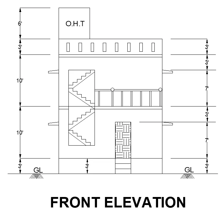
- The Elevation drawing from the floor plan has the exact size and positions of the building walls, doors and the windows.
- In the elevation view the O.H.T can be seen as a height of 6' from the top the parapet wall and the sunshades are can be seen at the height of 7' from the plinth level.
- From the G.L to Plinth level it has a height of 3' , from plinth level to the lintel level its has a height of 7' and form the lintel level to the the roof level it has a height of 10'.
- The Front elevation contains the staircase view from ouside the building through the glass window provided upto the first floor.
- The staircasewhich seen through the glass window has a dimensions tread size = 10" and the riser size = 7".
- And the Hand railing is provided at the first floor at the height of 3' from the floor level.
C.) SECTION : - BB
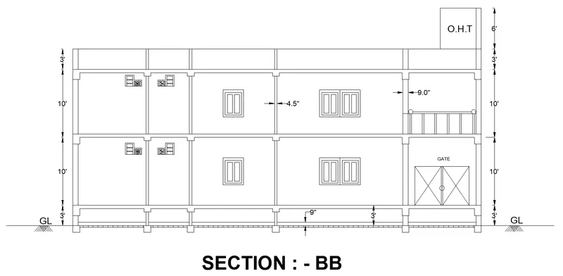
- In section:-BB drafting view we can see the cross section part of the floor plan with sectional line provided.
- It contains the exact size of the walls, windows and doors of the sectional floor plan.
- And the Hand railing is provided at the first floor at the height of 3' from the floor level.
- In the section :- BB view, the O.H.T can be seen as a height of 6' from the top the parapet wall and the sunshades are cannot be seen due to its doesn't contain sunshades inbetween the section line.
- It show the cross sectional view of the beams and columns of the buiding from the G.L to the parapet wall.
D.) SECTION :- AA
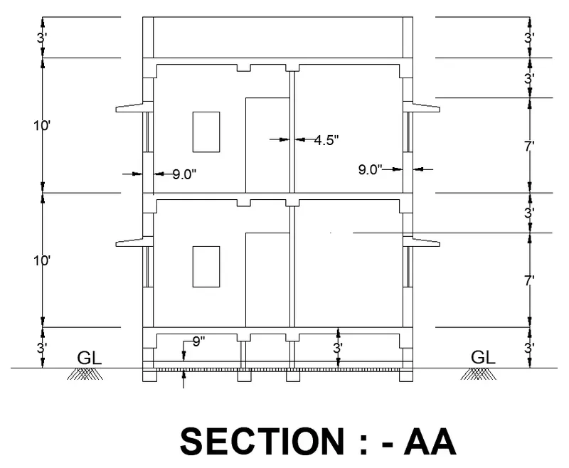
- In section:-AA drafting view we can see the cross section part of the floor plan with sectional line provided.
- It contains the exact size of the walls, windows and doors of the sectional floor plan.
- The door is provided upto the lintel level as 7' from the floor level and the kitchen counter opening can be seen and it has the height of 3' from the floor level.
- In the section :- AA view, the O.H.T cannot be seen due to the O.H.T didn't positioned inbetween the section line. and the sunshades can be seen.
- It show the cross sectional view of the beams and columns of the buiding from the G.L to the parapet wall.
2. STRUCTURAL DRAWING :
A.) COLUMN DETAILS :
- In the columns details , the columns are provided at the intersections of the beams or wall of the floor plan.
- The column size of 9"x9" is provided all over the buildings except the portico area and the balcony size 1' x 1'6".
- Due to the Balcony provided at the first floor of the building and it will be constructed by cantilever beam and one way slab.
- The columns are hatched to specify it special from the other structures.
B.) BEAM DETAILS :
- The beam details are created by connecting all the columns and where are the partition walls are to be provided in the floor plan.
- The beam size of this plan is 9"x1'6" and in large floor area with high inner spacings then the beam should be created between the beams arount it.
C.) FOOTING DETAILS :
- The footings of the plan is provided around the column structure as a required area of the footings to be provided.
- The area of the footing and the excavation is differ for the column size of 9"x9" and 9"x1'6".
- For 9"x9" sized column the footing size was 4'x4' and for the 9"x1'6" sized column the footing size was given as 4'x6'.
