Project 1 _Creating an Architectural plan for the provided plot size and develop relevant basic structural drawings
AUTOCAD PROJECT - 1
AIM:
To create an own Architectural drawing consisting of Floor plan, Elevations and Sections for the plot size 60'x20' and also create the structural drawings for Column, Footing and Beam. Explain the procedure step by step and display the result.
INTRODUCTION:
AutoCAD is a computer aided design software and drafting software application.
In this project, i have used various commands like,
* Block - I have made the direction symbols into a single block and named it as direction.
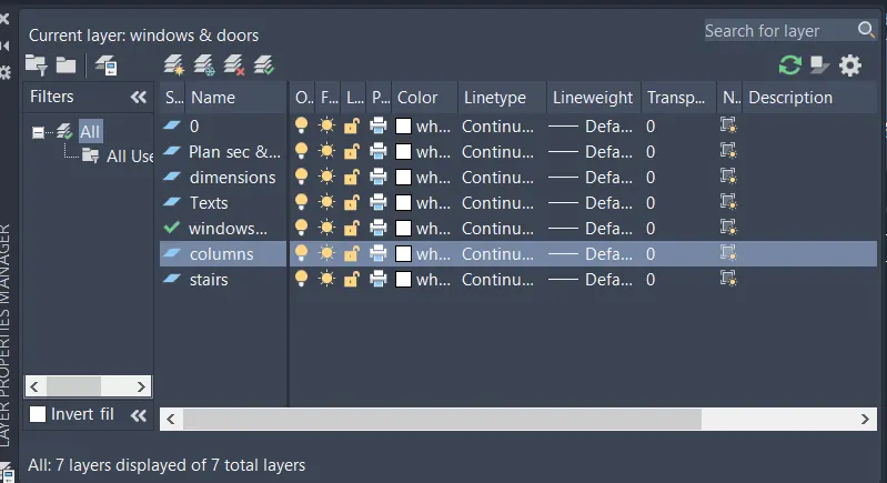
* LAYERS - created individual layers for Plan and Sections, windows and doors, Dimensions, and texts.
* Line,polyline,XLine - to create plan, sections, elevations, column-footing layout and beam layout.
* Dtext, Multi-leader - to mention the texts.
* Commands DIM Linear, DIM Continue - to create the Dimension lines.
* Hatch - to fill columns and also used in elevation drawing.
* Copy - to create objects.
* Fillet, Trim/erase, Offset, trim, ED - are regularly used at various places to complete the diagrams.
In the next step, the procedure is explained perfectly.
PROCEDURE:
- Open AutoCAD software
- Start from scratch
- Set the units to engineering and select ok
- Set limits as lower left corner (0,0) and upper right corner (500',500')
- Go to layer properties < create new layers < name the layers for reference < close
- Using the commands line and Dtext, i have created the directions.
- Then, Using the BLOCK command, i made it to a single block and named it as directions.

- Using the line Command, i drew the plot boundary of 60'x20'.
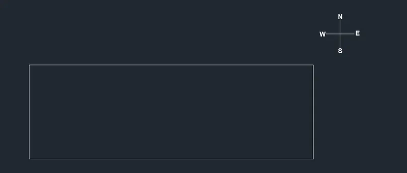
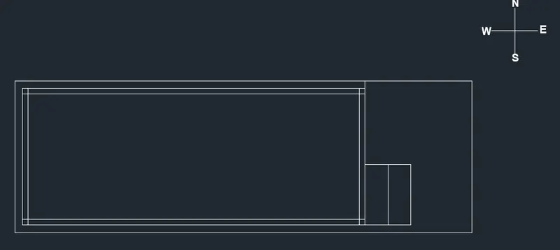
- The building's main entrance is facing the East direction.
- Using the commands line, offset, fillet and trim
- Starting from the East, the car parking is planned at 14'x10'6", Lawn area for about 7'6"x8'6" and stairs for about 6'x8'.
- And the building area is drawn leaving 1' offset distance in the North, West and South directions.
- After providing the offset distance, the floor dimensions comes about 45'x18' including walls.
- Outer walls at 9" thickness and inner walls at 4.5" thickness is provided.
- I have changed the linetype into SHORT-DASH for the plot boundary and adjusted the scale for better visibility.
- Now, using the commands Line, polyline, offset, fillet and trim, I have created my own plan for the project.
- It is planned as per VASTHU.
- The room dimensions are mentioned in the next step.
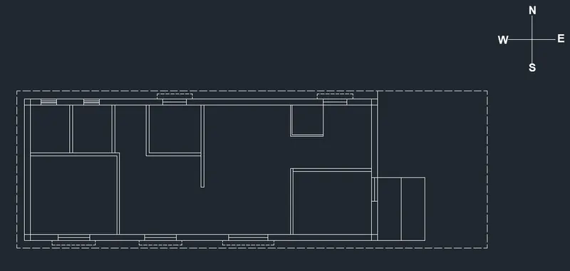
- Here, using the line and trim command, i have provided the door spaces as required.
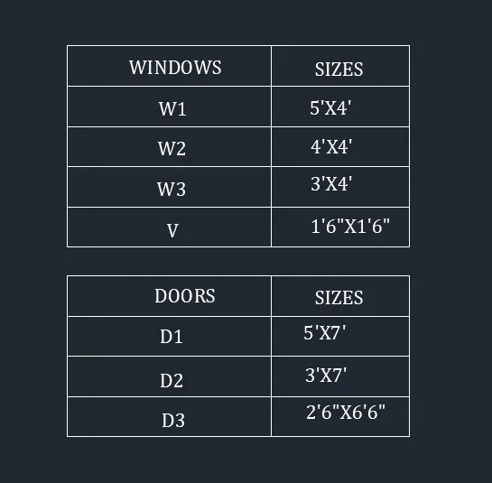
- The Door and Window dimensions are mentioned in the upcoming steps. (Please refer to Tabular column Provided in the upcoming steps).
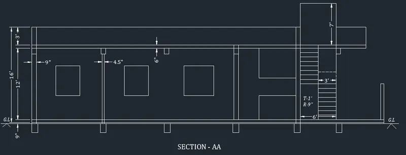
- Stairs are provided using line and offset command, with Tread - 1' and Rise - 9".
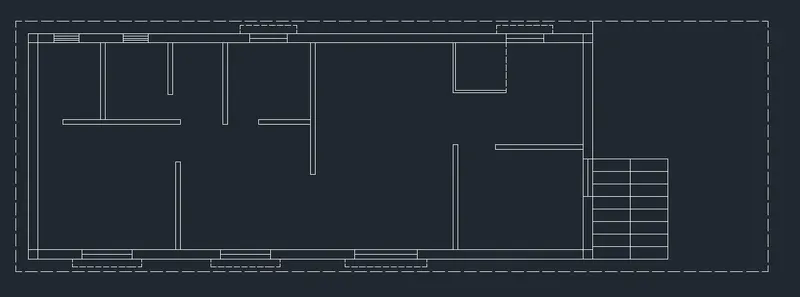
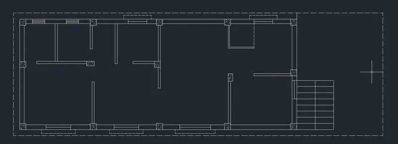
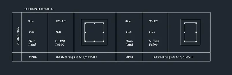
- Using line command, I have Created columns of sizes 12"x12" and 9"x12" and copy pasted it wherever required in the floor plan.
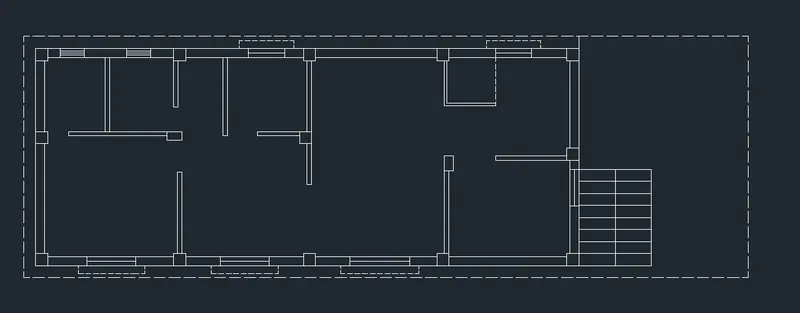
- Using the Hatch command, I have filled columns with AR-CONC and adjusted the scale for better visibility.
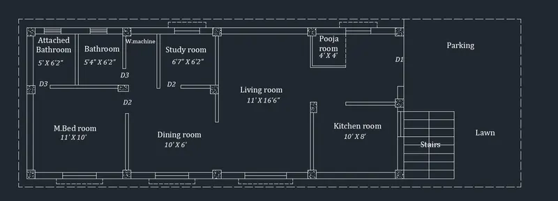
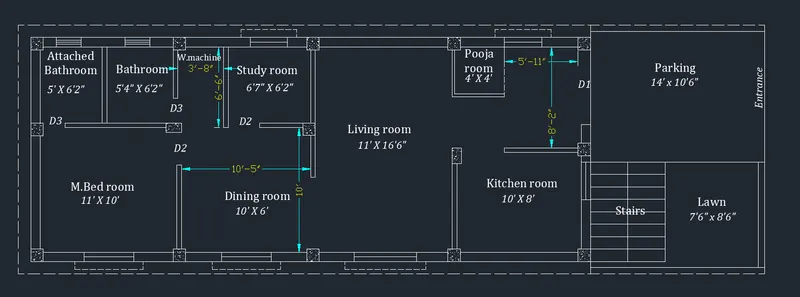
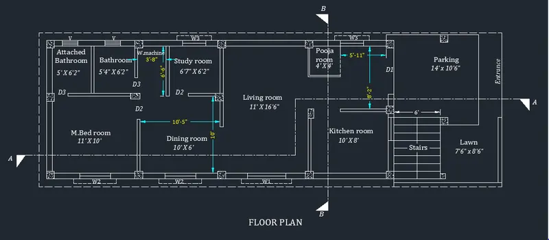
- Using the DText command, I have mentioned the names for each rooms, spaces, doors, windows and the dimensions for all the rooms.
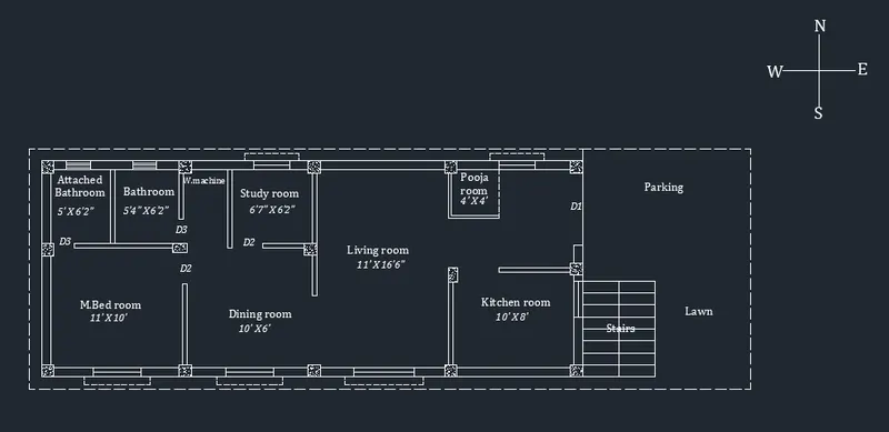
- Using the commands line, offset, fillet, trim and DText, the compound entrance is created with 6" thickness wall also the car parking and lawn area is surrounded by 6" thickness compound wall.
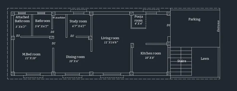
- Using the DIM-LIN command, I have mentioned the dimensions in the additional spaces and changed its colors for better view.
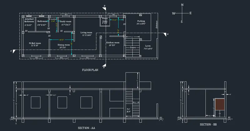
- Using the linetype LONG-DASH SHORT-DASH, I have cut the plan into 2 sections, SECTION - AA and SECTION - BB.
- Using the commands Line, polyline, offset, fillet and trim, I have created the sectional view for the Section -AA, provided windows as per the plan, kitchen space as planned and stairs as in the plan.
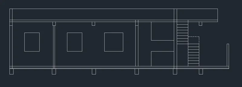
- Using the commands DIM-LIN, I have provided dimensions wherever required.
- And Using DText command, the Name is given in the bottom and staircase dimensions are mentioned.
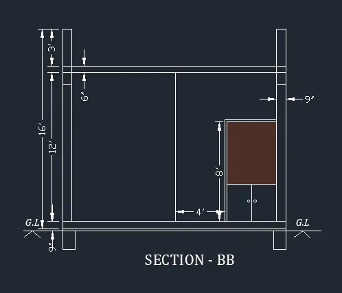
- Using the commands Line, polyline, offset, fillet, trim and hatch, I have created the sectional view for the Section -BB.
- Dimensions are given using the DIM-LIN command.
- Using DText command, the name is given in the bottom.
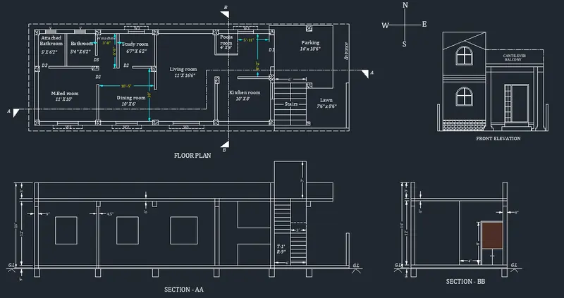
- The following image shows the Floor plan and sections A & B, together.
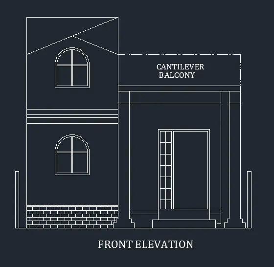
- Using the commands Line, polyline, offset, fillet, trim and hatch, I have created the FRONT ELEVATION for the building.
- The Stair room windows are 3'x3'6"
- The Main door+glass window dimensions are 4'6" x 7'.
- The compound wall height is 5' with 6" thickness.
- And, using DText command, the text and name is given.
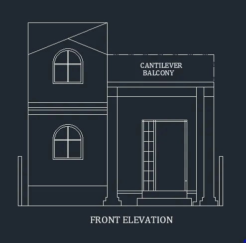
- Brick Hatch is used for 2' height from the ground for aesthetic purpose.
- The following image shows the Floor plan, Front Elevation and sections A & B, together.
- Go to LAYER properties, except COLUMNS layer lock all the other layers.
- Now, using Copy command, copy all the columns, plot boundary and paste it parallely above the floor plan.
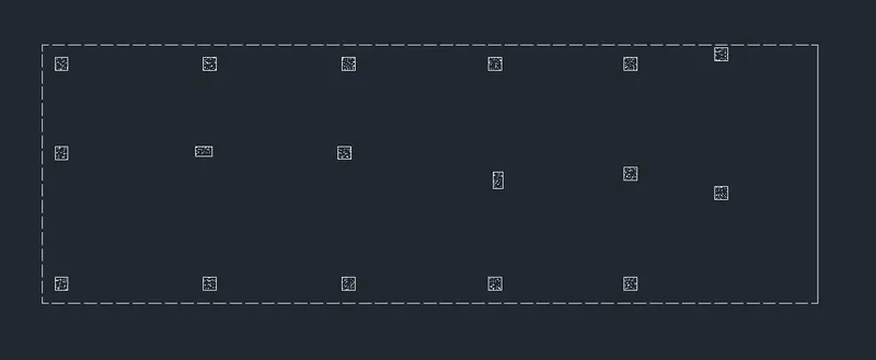
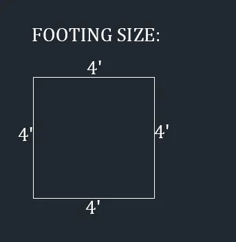
- Using the line command, the square footing of size 4'x4' is provided for all the columns except for staircase column where footing of size 3'x3' is provided.
- Using the CENTERLINE LineType, the grid lines are provided.
- Using the DIM-LIN and DIM-CONTINUE command, the dimensions between the grid lines are mentioned.
- Also using the DIM-LIN command, the column positions in the footing is mentioned.
- Using DText command, the Grid names and title is given.
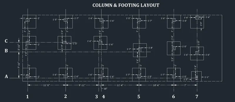
- For better visibility, I have provided colors for grid lines and dimensions between grid lines.
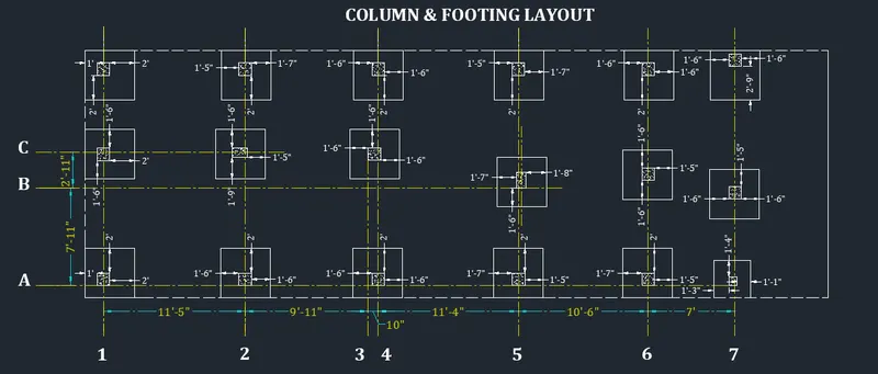
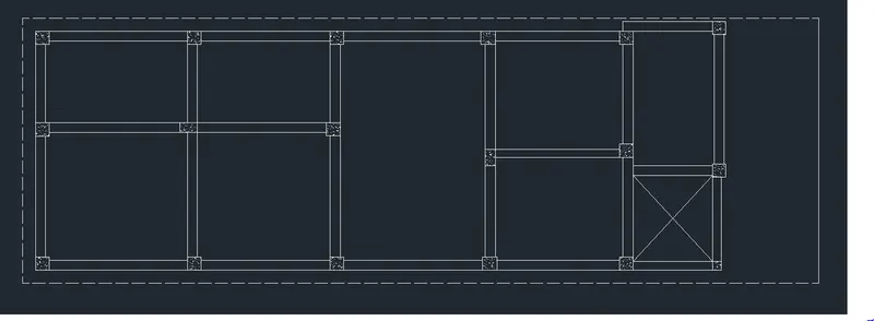
- Go to LAYER properties, except COLUMNS layer lock all the other layers.
- Now, using Copy command, copy all the columns, plot boundary and paste it parallely.
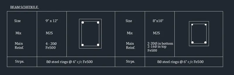
- Using the line command, connect the columns with beams of 9" width.
- Using the DIM-LIN and DIM-CONTINUE command, the Center-to-Center distance between each beams are mentioned.
- Using the DText command, the beam names and title of the layout is mentioned.
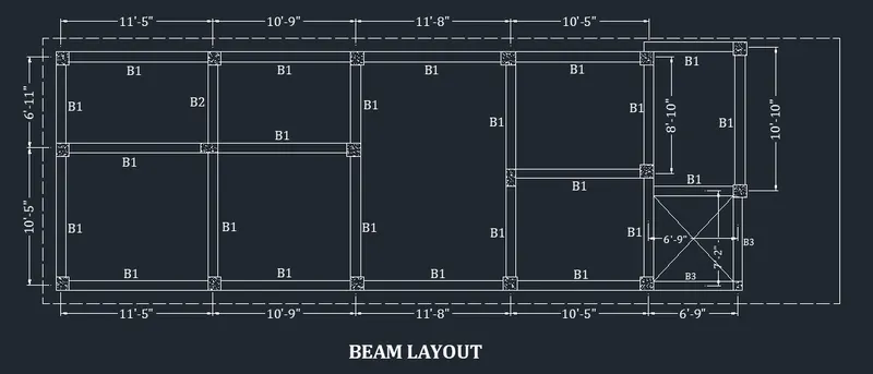
- Using the commands Line, Offset, Circle, Hatch and DText, the
- Column Schedule
- Beam Schedule and
- Footing Size is mentioned.
- Using the commands Line and Dtext, a tabular column is created showing the Doors and Windows sizes.
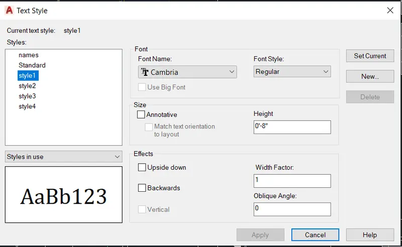
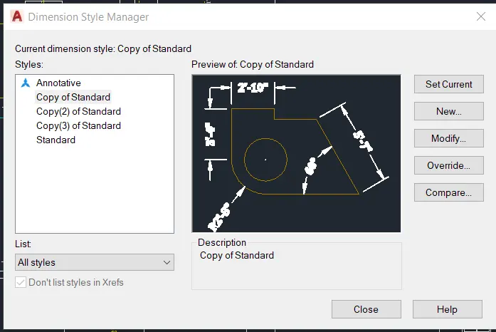
- Various Annotation styles created and used throughout the drawing is shown below,
RESULT: