Project 1 _Creating an Architectural plan for the provided plot size and develop relevant basic structural drawings
Aim- To draw the 2d plan of given dimensions and draw its elevation sectional view and structural drawing
Procedure-
2d plan
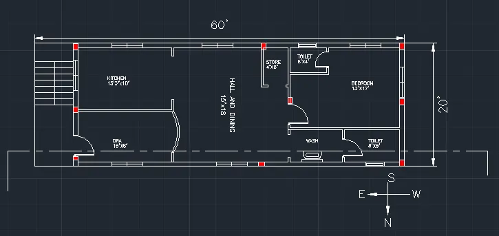
We have the dimensions are 60'x20'
Firstly draw the rectangle of @60',20'
Then offset the outer wall of 9 inches
Then explode the entire drawing
Firstlt draw the kitchen which should be in SE direction according your convinient direction
So offset litchen as 15,x10'
Then the remaining is drawing room
Then offset for hall and dining of 15'x48'
You can place seating in the hall according to convinence
Then draw the bedroom of 13'x14'
And attached bathroom of minimum nominal dimensions
Then draw common toilet of lengths 8'x5'
The remaining area is wash area for washingmachine and other things
Then draw store room which is attached to bedroom of nominam dimensions if required
Then trim for doors of lengths
Main door length 3.3'
Remaining doors length 3'
Draw door panels and swings and place
Draw windows and ventilators of 5' and 3' lengths and place
Name all the room with DT command and give dimensions
And give stair case at SE corner of 3' thread
Place the coloumns wherever required
ELEVATION-
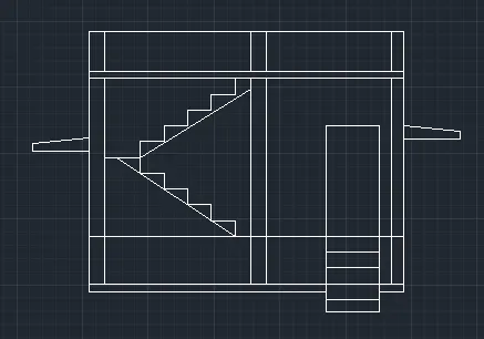
Project all the coloumns doors using xl command
Then draw a line as base
Offsset for 6" for pcc, 3' for basement and stairs at door
Then offset for door of 7'
Then draw the stairs
Draw stairs in front of the door
Then draw the lintels which are visible
Then draw the parapet wall
SECTION
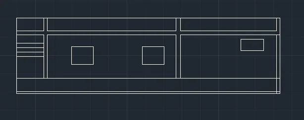
The section is cut as shown in 2d plan
From that it is visible of
As usual project all coloumns windown and ventilators
Offset for basemant of 3'
Then offset for slab10'
Then for sslab thickness of 5"
Then for parapet wall of 3'
Then offset for windows and ventilators
Trim all the unnecessary lines and form windows of halls and ventilator for bathroom
Then draw the steps towards up which are visible
Coloumn Schedule
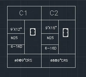
Draw the table of required dimensions
Then draw the coloumns in it of required size of @9x12 and @9x15
Then draw the reinforcement and stirrups
Then give the detailing of reinforcement and spacing and quantity
And also give the concrete mix
Beam schedule
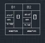
It is same as the coloumn schedule
Draw the table using the line command of desired dimensions
Then draw the beams of lengths 9x12 and 9x15
Then give the reinforcements and stirrups
Then give the detailing of it
Beam numbers
Then reinforcement details such as sizes no of bars and spacing and bar sizes
Then give the concrete mix
Footing
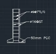
Draw the footing layout
Then give the reinforcement
Main bars and stirrups
Give the height of pcc and footing size
Then give reinforcement detailing
Main bars numbers
Stirrups spacing
Cover to be provided