Project 1 _Creating an Architectural plan for the provided plot size and develop relevant basic structural drawings
AIM: TO DESIGN AND DRAFT A RESIDENTIAL BUILDING FOR THE GIVEN PLOT SIZE. AND TO CREATE A SECTION AND FRONT ELEVATION SHOWCASING ALL THE NECESSARY DETAILS OF THE BUILDING. ALSO, TO PROVIDE RELEVANT BASIC STRUCTURAL DRAWINGS FOR THE SAME.
INTRODUCTION:
Plot size is very important from the design point of view. Many important aspects of the buildings like orientation, aspect, prospect, directions, etc all depend on the plot size we have by our side. At the same time, plot size also allows us to give suitable dimensions to different building units. Therefore, one must be proficient with properly understanding the given plot size and then accordingly, analyze the approach of the structure. Hence, in this project, we have planned a residential building for the given plot size so as to efficiently accommodate all the essential units of the structure. In addition to the architectural layout of the building, basic relevant structural drawings like column and beam layout plans as well as footing locations are also planned in this project.
STEPWISE PROCEDURE:
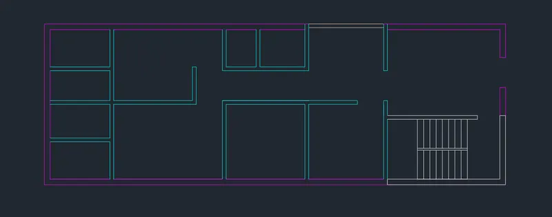
1. Planning the Building as per Given Plot Size that is 60' x 20'
- Draw the overall layout of the floor
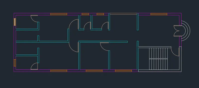
- Place Doors and Windows According to the Industry Standard Sizes
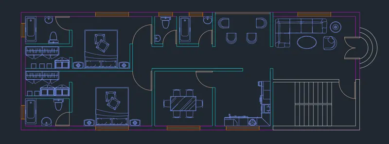
- Add Furnishes to Display the Utility Guidelines for All rooms of the Building
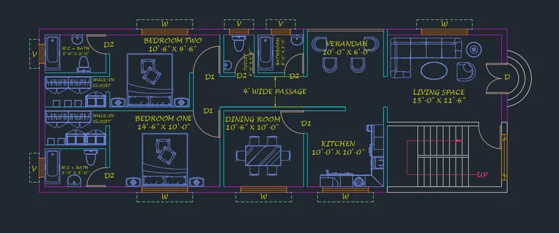
- Add texts to Notify Size of Each Unit
- Decide Column Locations and Orientation as per the Standards
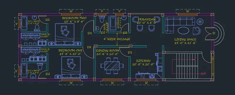
FINAL OUTPUT
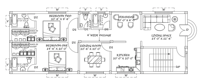
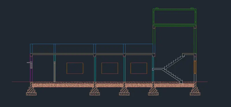
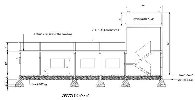
2. Drawing the Section Cutting Through the Staircase of the Building.
- Draft the Section Line Cutting Through the Staircase (A->A)
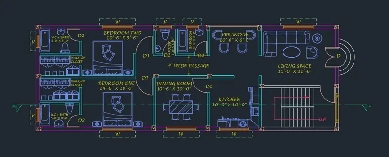
- Use Construction Lines to Locate the Section A->A and thus Draw the sectional layout at foundation level

- Project lines for different objects and draw the section for the floor
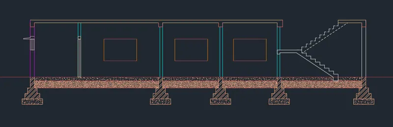
- Draft the parapet level and design the over head tank for the building
- Add dimensions to notify all the levels and height of the structure
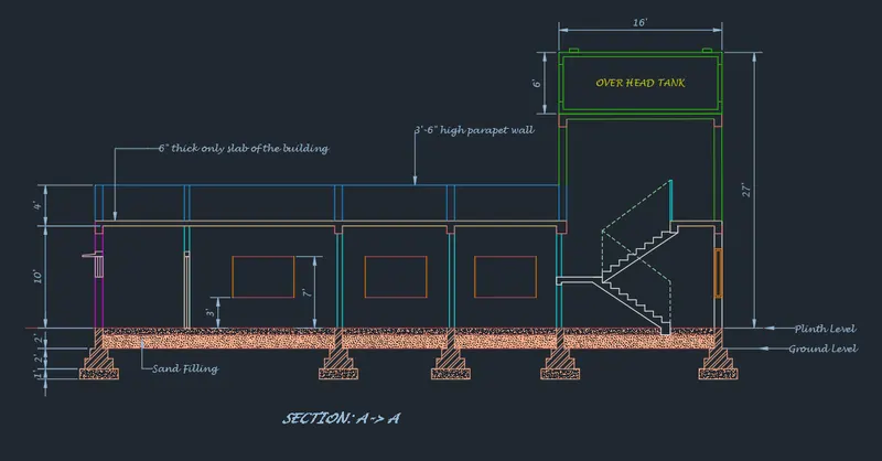
- Add railings for the staircase and complete the sectional elevation
FINAL OUTPUT
3. Drawing the Front Elevation from the East Direction to Project the Outward View of the Structure.
- Use Construction Lines and draft the outlook
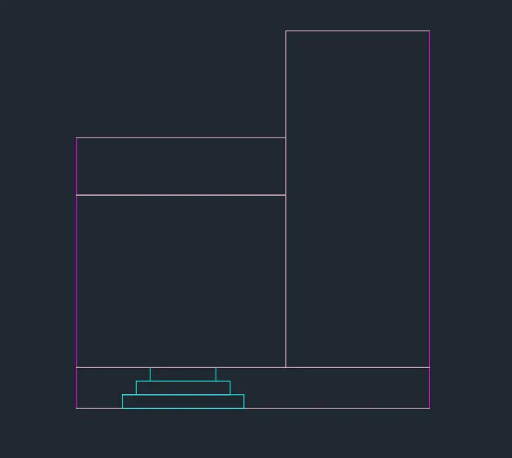
- Add the front door and staircase grill
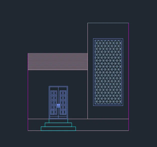
- Do the finishing touches and complete the front elevation
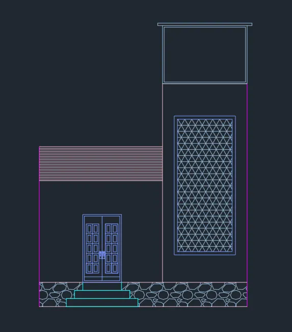
FINAL OUTPUT
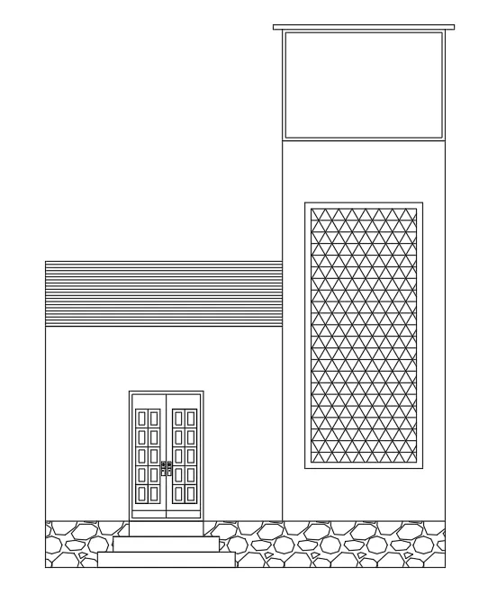
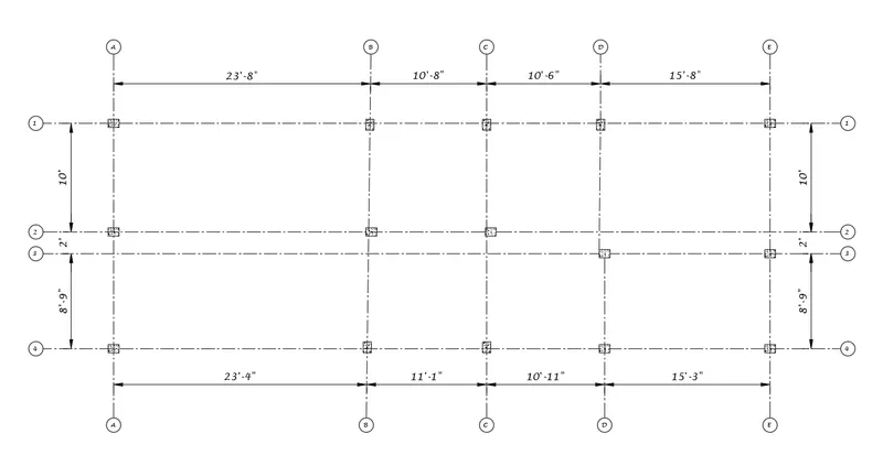
4. Prepare the Column Layout Grid Also Known as the Centerline Plan
- Use layer style manager to attain only columns layer

- Draft the grid using centerlines

- Give notations to each column and add dimensions to explain the center to center distance between columns
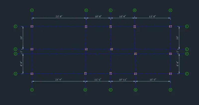
FINAL OUTPUT
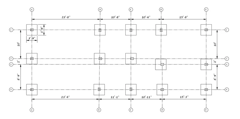
5. Specifying the Footing Locations Through Footing Placement.
- Place square footings of size 3'-9" x 3'-9" to each column drawn in the centerline plan
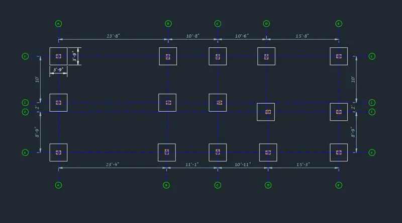
FINAL OUTPUT
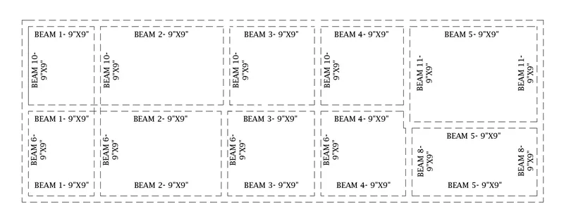
6. Drawing the Beam Layout Plan
- Use the layer style manager and obtain a beam layout plan from the floor
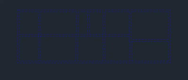
- Give notation for each beam in the layout
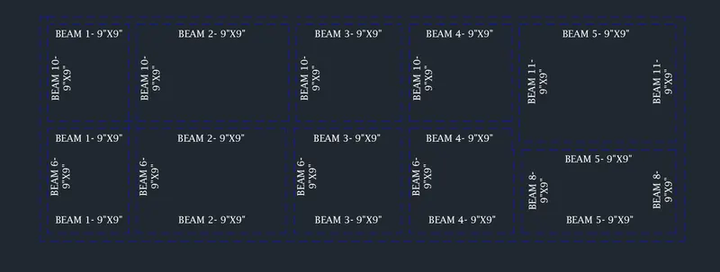
FINAL OUTPUT
CONCLUSION
To sum it up, drawing the floor plan within the specified space is simple but it does need some creativity to utilize every space of the corner efficiently. You need to explore different options before deciding on how you will go ahead with the building. And once you complete the floor plan, everything else is a seamless process as the floor plan is the base of further drawings. Henceforth, you can draw section, elevation, column layout plan, footing placement, and beam layout plan observing the steps followed in this project.