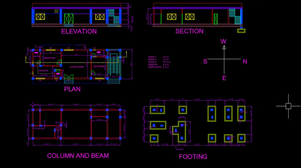
Project 1 _Creating an Architectural plan for the provided plot size and develop relevant basic structural drawings
Q. Design and Draft a layout of a residential building with the following details:
a. Plot Size: 60’x20’(18.3m x6m)
b. Orientation- Facing East
c. Develop the following: 1. Architectural Drawing (Floor Plan, Elevations, and Sections) 2. Structural Drawing (Column, Bean, Footing Plan)
Ans:
Aim: To draw the PLAN, SECTION, ELEVATION of a east faced building of plot size 60’ X 40’ using AutoCAD software
Procedure:
Step 1 Basic settings
<!-- [if !supportLists]-->· <!--[endif]-->Open AutoCAD
<!-- [if !supportLists]-->· <!--[endif]-->Open new drawing
<!-- [if !supportLists]-->· <!--[endif]-->Set units (measurements as decimal, precision to 0.0 , angle as decimal degree)
<!-- [if !supportLists]-->· <!--[endif]-->Enable Ortho mode on
Step 2
<!-- [if !supportLists]-->· <!--[endif]-->Enter command dimstyle and click on modify
<!-- [if !supportLists]-->· <!--[endif]-->Set unit to decimal and precision to 0.0
Step 3: outline
<!-- [if !supportLists]-->· <!--[endif]-->Use X-line by typing “XL” in command box
<!-- [if !supportLists]-->· <!--[endif]-->Select vertical and plot a line by using cursor
<!-- [if !supportLists]-->· <!--[endif]-->Use X-line by typing “XL” in command box
<!-- [if !supportLists]-->· <!--[endif]-->Select horizontal and plot a line by using cursor
Step 4: layers
<!-- [if !supportLists]-->· <!--[endif]-->Go to layer properties from home ribbon
<!-- [if !supportLists]-->· <!--[endif]-->Now select new layer
<!-- [if !supportLists]-->· <!--[endif]-->Rename it as outline and assign colour
<!-- [if !supportLists]-->· <!--[endif]-->Do the same for diff layers and assign diff colors
<!-- [if !supportLists]-->· <!--[endif]-->Press enter and close
<!-- [if !supportLists]-->· <!--[endif]-->Now select the lines and assign the layers from layer panel in home ribbon
Step 5: drawing of plan
<!-- [if !supportLists]-->· <!--[endif]-->Use “xline” command and draw vertical and horizontal construction lines
<!-- [if !supportLists]-->· <!--[endif]-->Use “o” command to create offset lines by providing sufficient lengths
<!-- [if !supportLists]-->· <!--[endif]-->Use “line” tool to draw the lines at required places
<!-- [if !supportLists]-->· <!--[endif]-->Turn on the object snap to locate mid and end points easily
<!-- [if !supportLists]-->· <!--[endif]-->Use “trim” tool to erase the unwanted portion of lines
<!-- [if !supportLists]-->· <!--[endif]-->Use “c” in command box to create circles at any place
<!-- [if !supportLists]-->· <!--[endif]-->Use chamfer tool and select angle and give value to provide curve edjes
<!-- [if !supportLists]-->· <!--[endif]-->Draw doors and windows of different lengths as per requirement
<!-- [if !supportLists]-->· <!--[endif]-->By using different tools like (mirror , rotate , copy) create more number as required
<!-- [if !supportLists]-->· <!--[endif]-->Use “move” tool to move the item to a particular place
<!-- [if !supportLists]-->· <!--[endif]-->Select line tool and draw the section AA and BB lines as given in the diagram
Step 6 : Drawing of section , elevation, column and footing drawings
<!-- [if !supportLists]-->· <!--[endif]-->Use “X line” command to project the walls , columns and other wanted information from PLAN to section
<!-- [if !supportLists]-->· <!--[endif]-->Use “o” command to create offset lines by providing sufficient lengths
<!-- [if !supportLists]-->· <!--[endif]-->Use “line” tool to draw the lines at required places
<!-- [if !supportLists]-->· <!--[endif]-->Use “trim” tool to erase the unwanted portion of lines
<!-- [if !supportLists]-->· <!--[endif]-->Use “c” in command box to create circles at any place
<!-- [if !supportLists]-->· <!--[endif]-->Use chamfer tool and select angle and give value to provide curve edjes
<!-- [if !supportLists]-->· <!--[endif]-->Draw doors and windows of different lengths as given in diagram
<!-- [if !supportLists]-->· <!--[endif]-->By using different tools like (mirror , rotate , copy) create more number as required
<!-- [if !supportLists]-->· <!--[endif]-->Use “move” tool to move the item to a particular place
</>
< class>
</>
< class>Step 7: dimension
<!-- [if !supportLists]-->· <!--[endif]-->Select dimensions tool from ribbon
<!-- [if !supportLists]-->· <!--[endif]-->And give the all dimensions as given in diagram
Step 8: text
<!-- [if !supportLists]-->· <!--[endif]-->Select text tool by typing mtext in command box
<!-- [if !supportLists]-->· <!--[endif]-->Click the cursor at required points
<!-- [if !supportLists]-->· <!--[endif]-->Give the text as per requirement
<!-- [if !supportLists]-->· <!--[endif]-->Can change the height of text by right click on the text given and properties tab
RESULT: PLAN, SECTION, ELEVATION of a east faced building of plot size 60’ X 40’ using AutoCAD software is drawn and given below