Project 1 _Creating an Architectural plan for the provided plot size and develop relevant basic structural drawings
AIM
To design and draft a layout of a Residential building
Drawings Required: Floor plan,Sections,Elevation,Column Layout,Beam Layout ,Footing Layout
INTRODUCTION
AutoCAD is used to create 2D and 3D drawings,plans and models in a variety of industry such as architecture,engineering and construction.
Here,AutoCAD is used to draw a residential building layout.
The plot size :60' x 20'
Orientation :Facing East
- various commands in AutoCAD
- NEW
- UN
- LIMMAX
- XLINE
- LINE
- OFFSET
- TRIM
- ERASE
- COPY
- MOVE
- CIRCLE
- RECTANGLE
- FILLET
- LA
- DTEXT
- DIMLINEAR
- DIMCONTINUE
- MULTILEADER
- HATCH
- D-DIMENSTIONAL STYLE
- BLOCK
- INSERT
2.VASTHU Requirements
- Main Door - East
- Stairs -South-East
- Kitchen -South-East
- Pooja Room -North-East
- Living Area -Facing East
- Study Room -North-East
- Dinning Room -South-East
- Master Bedroom -South-West
- Attached Bathroom -North-West
- Bathroom -North-West
PROCEDURE
- Use command NEW ->Advanced Startup-> set the required units
- Or Set the required units using UNITS command.Here the unit system is ENGINEERING
- Set the limit of the sheet using LIMMAX command(35'0",24'9")
- Using the LINE Command,plot boundary of 60'x20' is drawn
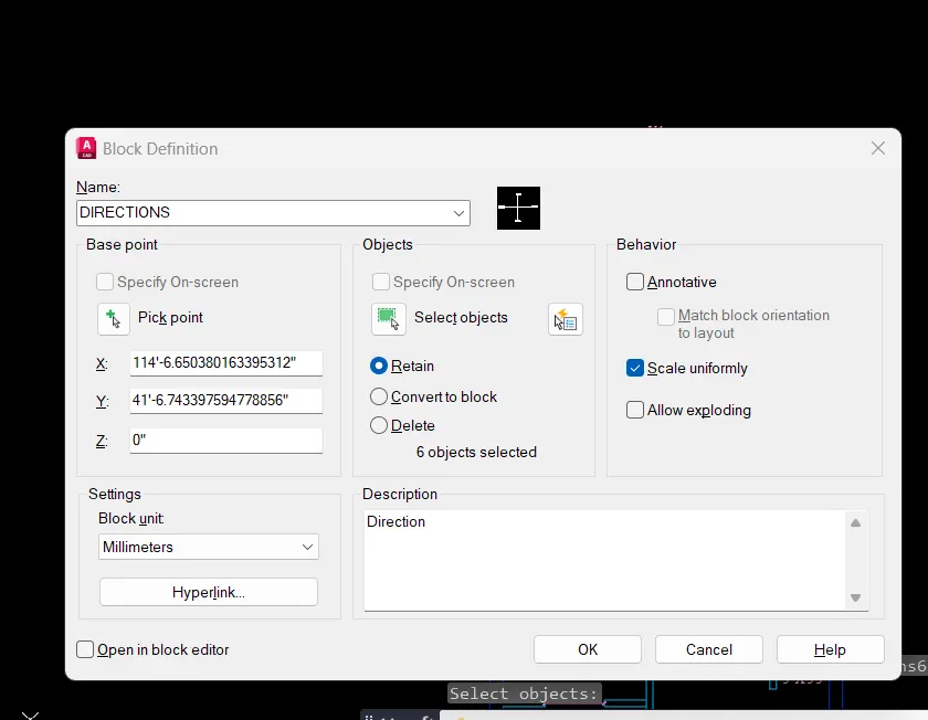
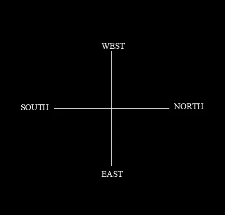
- Draw the directions in the sheet using the LINE and DTEXT command(The directions can be made a BLOCK)
- The building's main entrance is facing the East direction
- Size of the planned residential building is 20' x 43'
- A 20' x 10' space is left for Car parking as well as for Garden purpose
- XLINE command can be used to draw the infinte horizontal and vertical line
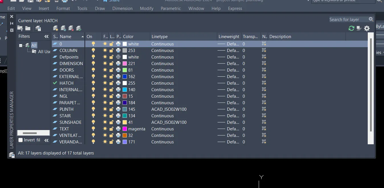
- Various layers have been created using the LA command ex:external walls layer,doors and windows layer,dimension layer,text layer etc.Different colours can be given to each of these layers.
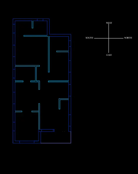
- Using the LINE command and the OFFSET command the prepared plan,section and elevation (Take projections from the plan) is drawn
- As required use the COPY,TRIM,MIRROR,CIRCLE,RECTANG,EXTEND command to draw the plan,section and elevation
- After the completion of the drawing various layers can be assigned to the drawing
- Do the dimensioning of the geometry using the DIMENSION command from the menu bar or using the DIMLINEAR command
- Continuation of the dimension can be done using the DIMCONTINUE command
- For customizing the dimensioning(height of dimension text,angle of dimension,dimension line size ,arrow size etc) use the command D
- From the RIBBON >Home>Text,the texting of the geometry can be done or by using the TEXT command
- From the RIBBON > ANNOTATE>MULTILEADER can be used wherever leaders are required
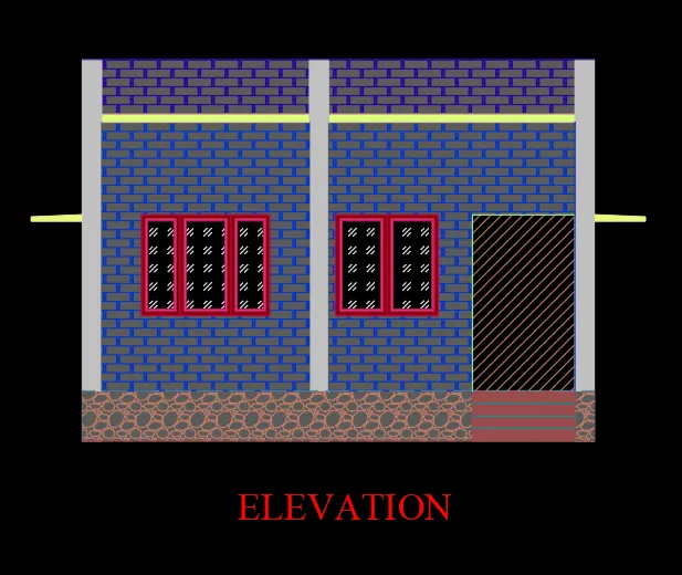
- HATCHING can be done wherever required by using the command h ->click on the OPTIONS button and select the required type of hatching pattern (For elevation,section drawing hatching is used )
- BLOCK command can be used to make drawings convert to block (Windows,Doors (Dynmaic block) and Ventilator have been converted to BLOCKS)
- INSERT command can be used for the block insertion
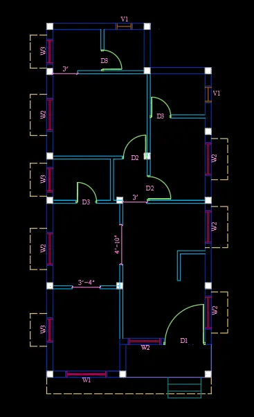
Dimension of various components in the plan
- Dimensions of Windows
| WINDOWS/VENTILATOR | SIZE |
| W1 | 5'X 4' |
| W2 | 4' X 4' |
| W3 | 3' X 3' |
| V | 2' X 1'6" |
- Dimensions of Doors
| DOORS | SIZE |
| D1 |
5' X 7' |
| D2 |
3' X 7' |
| D3 | 2'6" X 7' |
- External Wall thickness :9"
- Internal wall thickness :4.5"
- Sunshade external projection :2'
- Tread :10"
- Riser :6"
AutoCAD WORK PROGRESS STEPS:
ARCHITECTURAL DRAWINGS
- Fixation of Directions
Directions made as a BLOCK
- Layer Creation
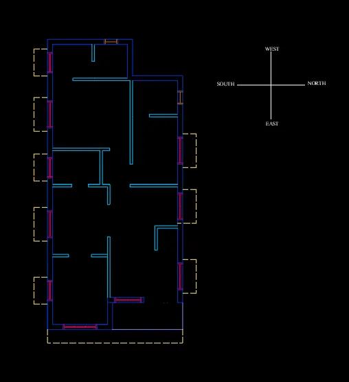
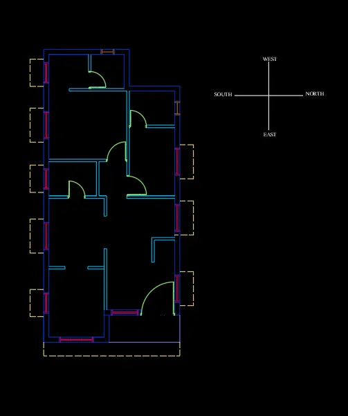
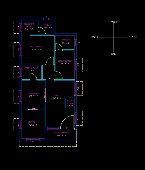
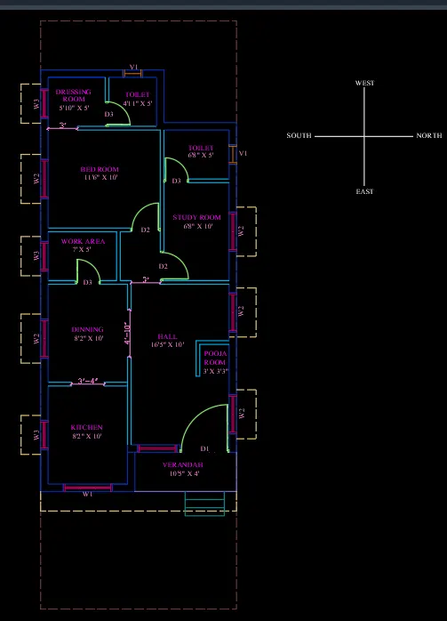
- Steps in Drafting of PLAN
- Steps in Drafting of SECTIONS
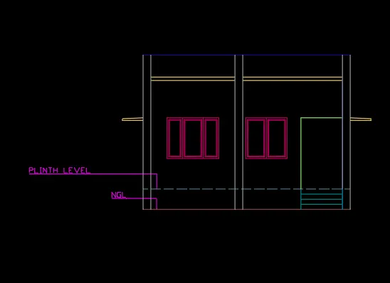
Section AA was chosen for drawing the elevation
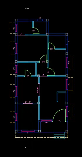
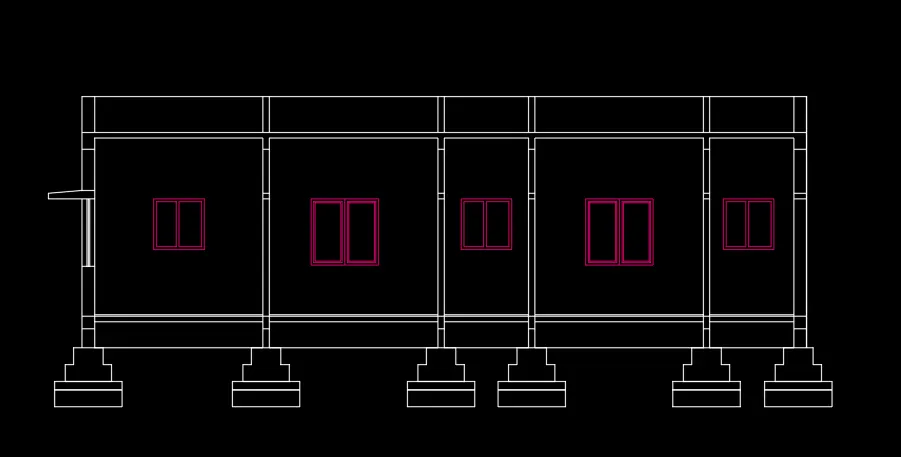
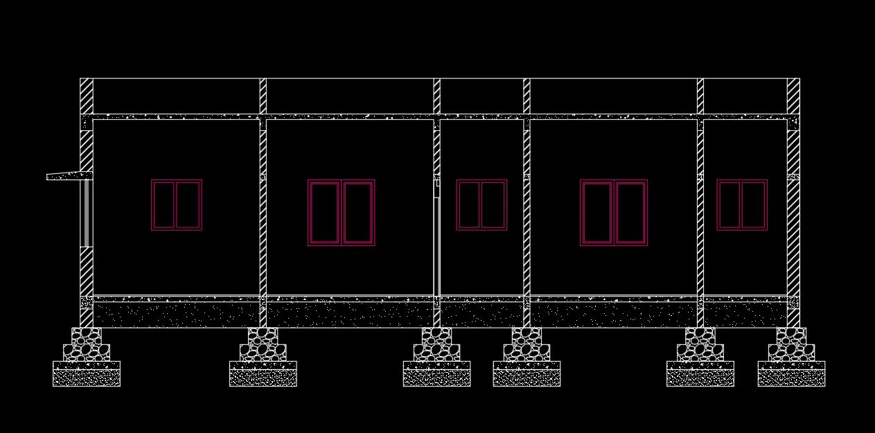
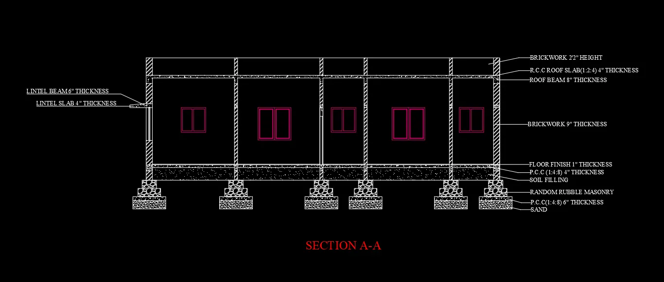
- Steps in Drafting of ELEVATION
Elevation can be drawn by projecting lines from the plan
Various Levels
NGL: Base Layer
Plinth Level:2'
Dimensions Measured from plinth level
Sill Level :2'11"
Lintel Level :6'11"
Room Height :10'10"
Sunshade :10'6"
Parapet wall thickness:2'2" (From Sunshade)
Column Cross section :9" x 9"
STRUCTURAL DRAWINGS
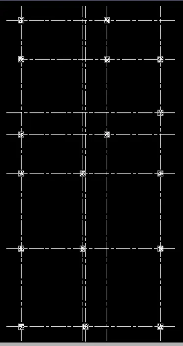
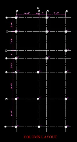
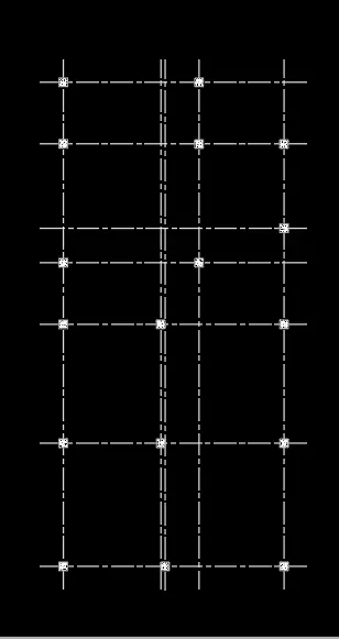
- Steps in drafting of COLUMN LAYOUT
- Create a layer for the columns
- Position the Column wherever nesessray in the plan
- The size of the column should also be fixed
- Here, as a trial the size(Cross section)of the column is assumed as 9" x 9"
- Except the column layer,turn off all the other layers
- Using the COPY Command,Copy the column location
- Using Construction Lines,draw the central line of every columns
- Do the dimensioning of the geometry using the DIMENSION command from the menu bar or using the DIMLINEAR command
- Continuation of the dimension can be done using the DIMCONTINUE command
- For customizing the dimensioning(height of dimension text,angle of dimension,dimension line size ,arrow size etc) use the command D
- From the RIBBON > ANNOTATE>MULTILEADER can be used wherever leaders are required (Inorder to mark the central line positions)
- From the RIBBON >Home>Text,the texting of the geometry can be done or by using the TEXT command
2.Steps in drafting of BEAM LAYOUT
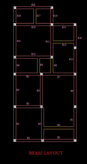
- Create a layer for the BEAMS
- For Primary beam,Secondary beam separte layers have been created
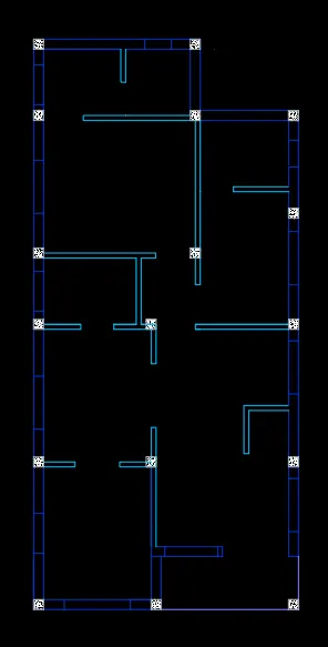
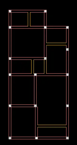
- Copy the position of the columns by turning off all the other layers except the layer of column and center line
- Draw beams wherever nesessary as per the plan
- Here,For a G+0 structure as an assumption the Plinth Beam dimension is taken as 9" x 9"
- Primary beam, Secondary beam size is taken by assumption as 9" x9"
- Beams can be drawn by taking offsets using OFFSET Command from the Central line of columns(4.5" offsets on both side of the column central line)
- From the RIBBON >Home>Text,the texting of the geometry can be done or by using the TEXT command
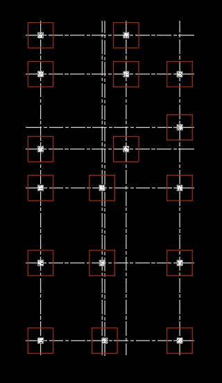
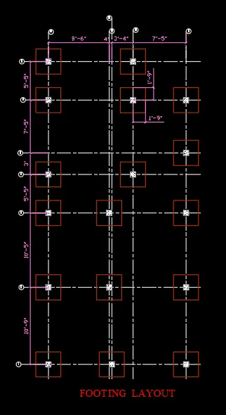
3.Steps in drafting of FOOTING LAYOUT
- Create a layer for the FOOTING
- Copy the position of the columns by turning off all the other layers except the layer of column and center line
- Here,For a G+0 structure the column size assumed was 9" x 9"
- For a column of 9" x 9" size,the footing size should be 3.5' x 3.5'
- Using the OFFSET Command the Footing can be drawn ( As required use the above mentioned COMMANDS)
- From the RIBBON >Home>Text,the texting of the geometry can be done or by using the TEXT command
RESULT
- A Residential plan Layout have been developed in the given plot size
- The following drawings have been developed:
Architectural Drawings -Plan,Section and Elevation
Structural Drawings -Column Layout,Beam Layout,Footing Layout