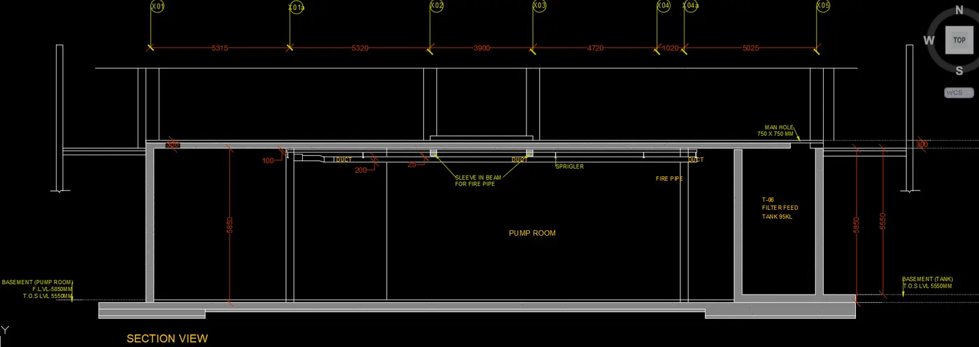
Creating Kitchen layout, Hatching of Architectural elements and sectional view of an Industrial Building in AutoCad
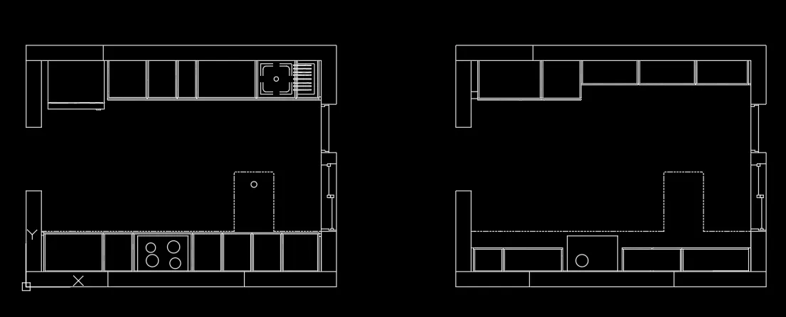
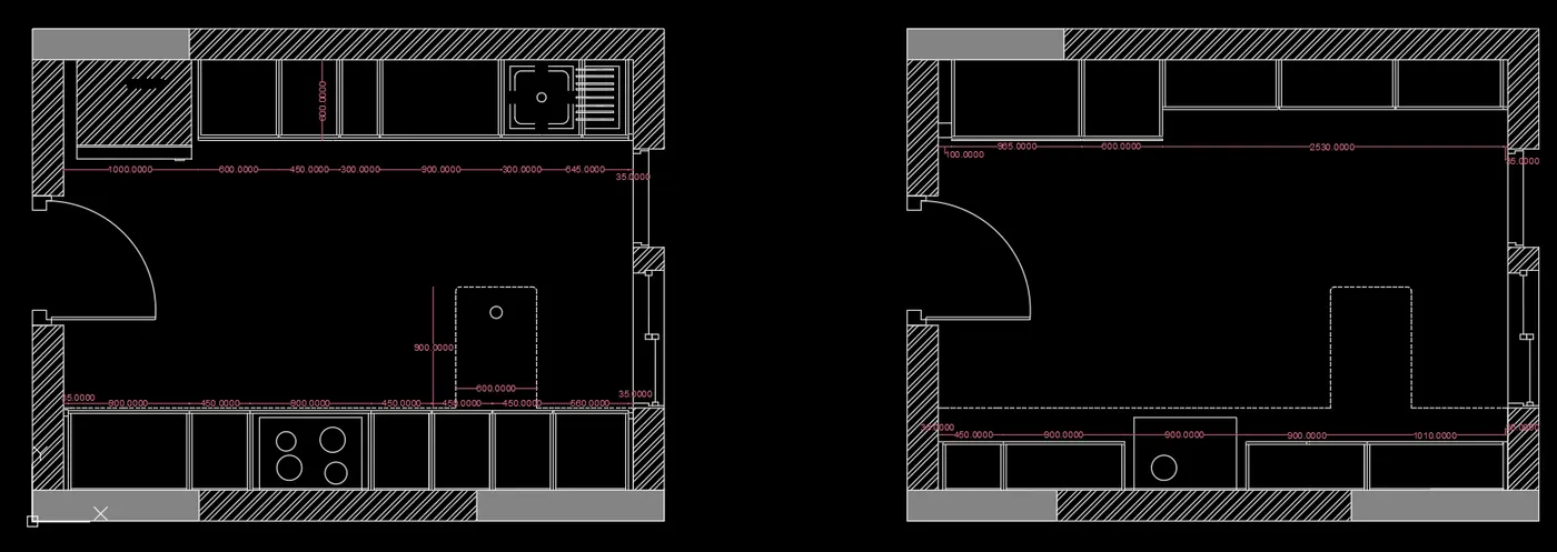
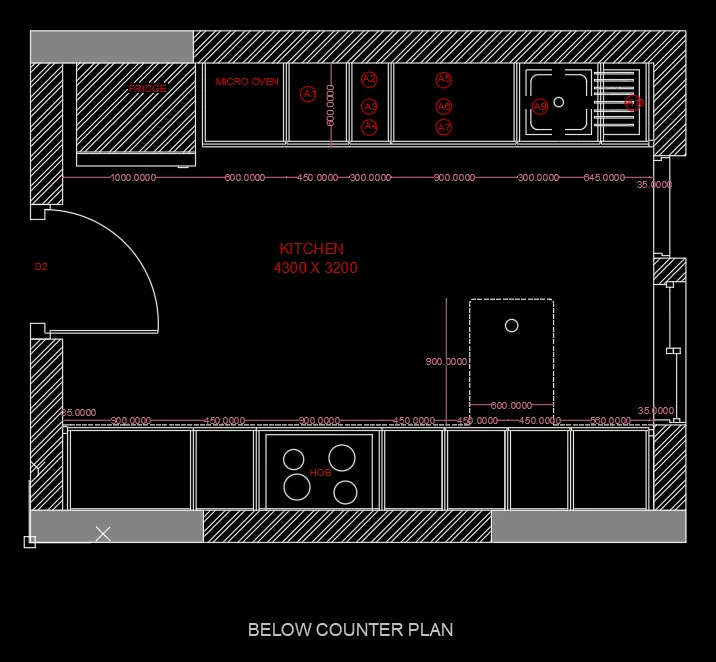
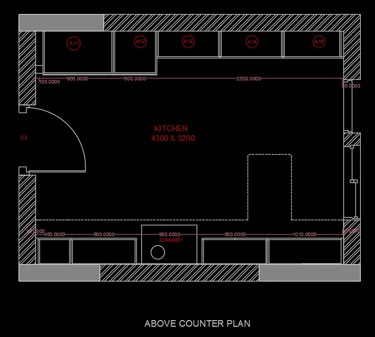
1.KITCHEN LAYOUT CREATION
PROCEDURE:
- Use command NEW ->Advanced Startup-> set the required units
- Or Set the required units using UNITS command.Here the unit system is Decimel
- Set the limit of the using LIMMAX command
- Various layers have been created using the LA command ex:0 Layer,Dimension Layer,Text Layer,Hatch Layer etc.Different colours can be given to each of these layers.
- XLINE command can be used to draw the infinte horizontal and vertical line
- Using the LINE command and the OFFSET command draw the required details
- As required use the COPY,TRIM,CIRCLE,RECTANG,EXTEND,FILLET command
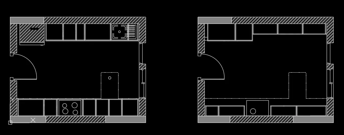
- HATCHING can be done wherever required by using the command h ->click on the OPTIONS button and select the required type of hatching pattern
- Do the dimensioning of the geometry using the DIMENSION command from the menu bar or using the DIMLINEAR command
- Continuation of the dimension can be done using the DIMCONTINUE command
- From the RIBBON >Home>Text,the texting of the geometry can be done or by using the TEXT command
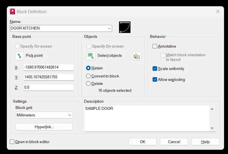
- For converting objects to block use the BLOCK command
- Here the door of the kitchen have been converted to block
- For insertion of the objects made as a block, INSERT command can be used

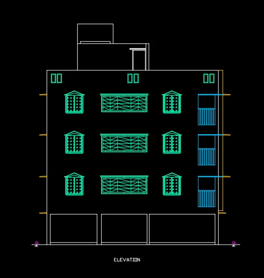
2.ELEVATION CREATION
PROCEDURE:
- Use command NEW ->Advanced Startup-> set the required units
- Or Set the required units using UNITS command.Here the unit system is Decimel
- Set the limit of the using LIMMAX command
- Various layers have been created using the LA command ex:0 Layer,Dimension Layer,Text Layer,Hatch Layer etc.Different colours can be given to each of these layers.
- XLINE command can be used to draw the infinte horizontal and vertical line
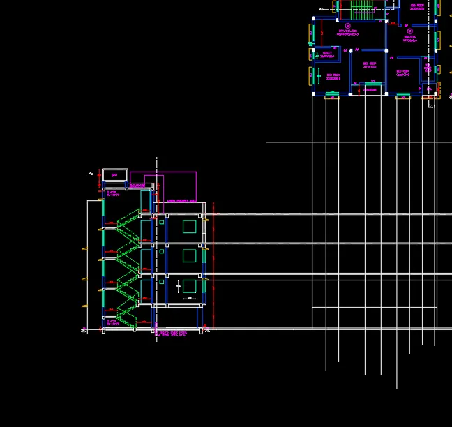
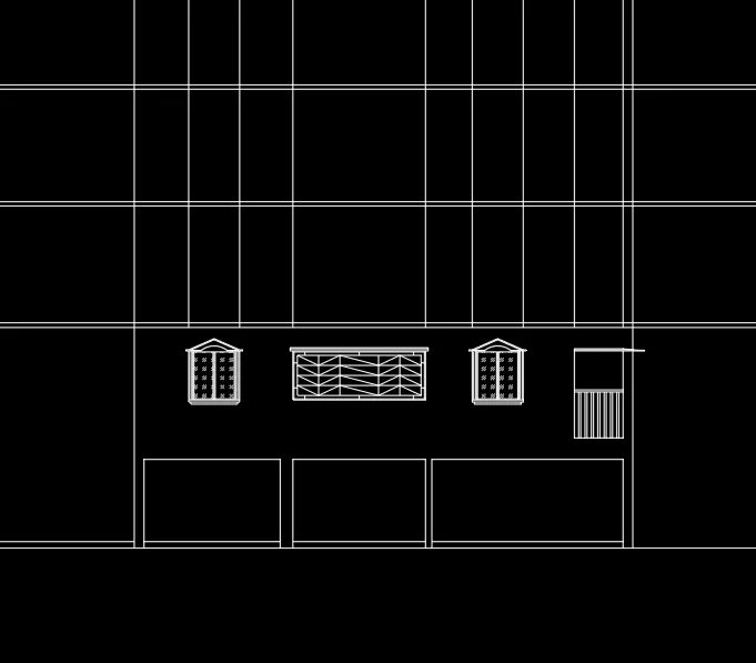
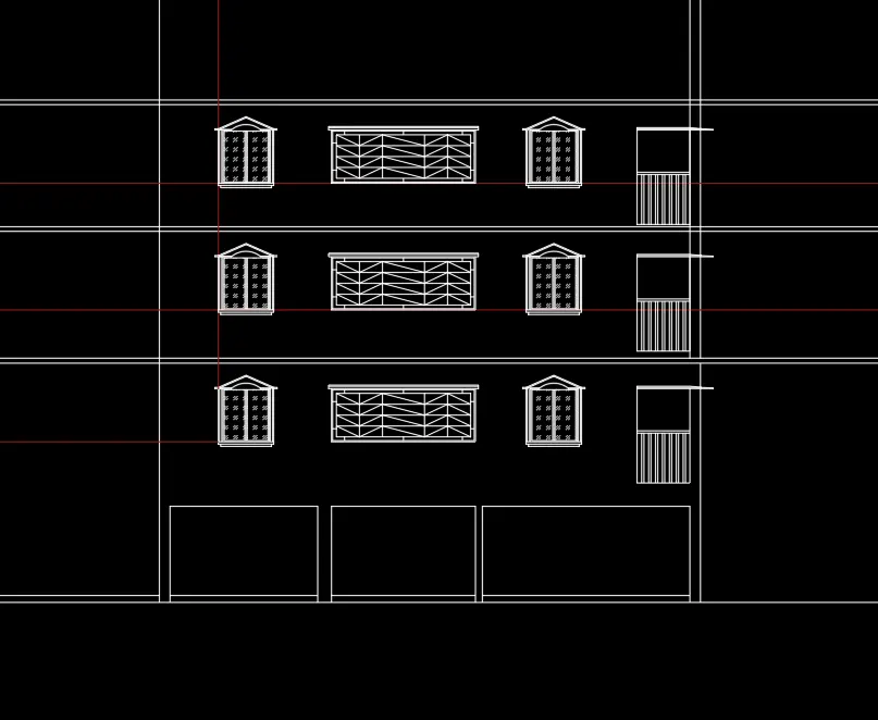
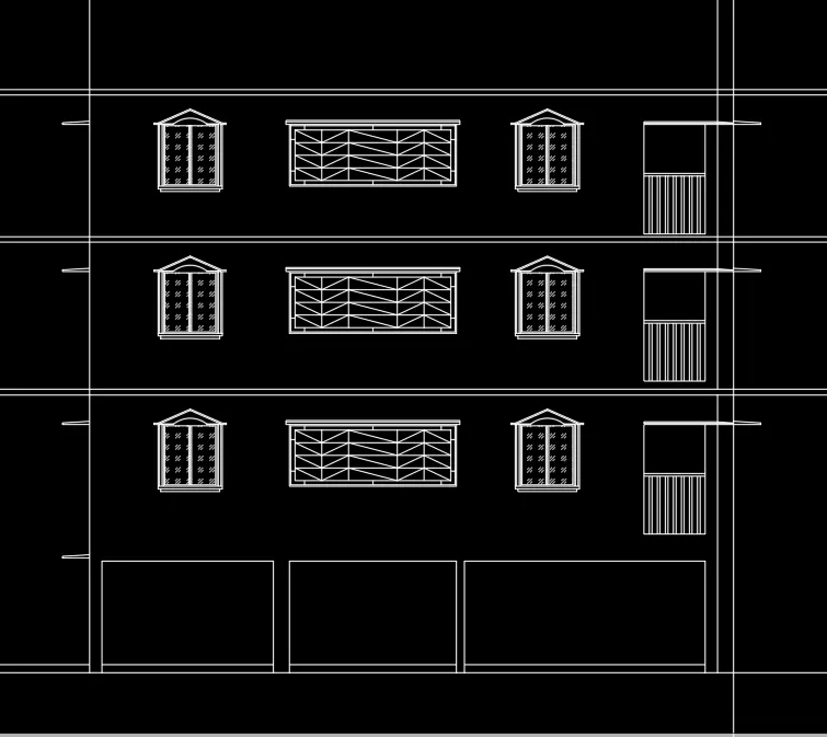
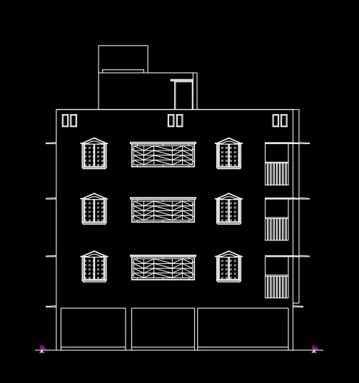
- Here We are asked to draw the elevation of a plan which we have done already in challenge 7
- so we can use that drawing for the dimensions
- To draw the elevation projection can be take from the plan and the sections
- Using the commands LINE,OFFSET,COPY,TRIM,RECTANG,EXTEND,MIFRROR,ERASE draw the required details
- HATCHING can be done wherever required by using the command h ->click on the OPTIONS button and select the required type of hatching pattern
- Do the dimensioning of the geometry using the DIMENSION command from the menu bar or using the DIMLINEAR command
- Continuation of the dimension can be done using the DIMCONTINUE command
- From the RIBBON >Home>Text,the texting of the geometry can be done or by using the TEXT command
- After the completion of the drawing, various layers can be assigned to the each of the components
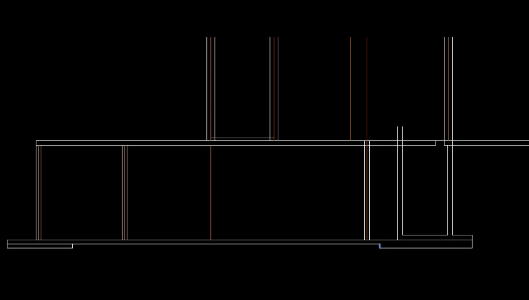
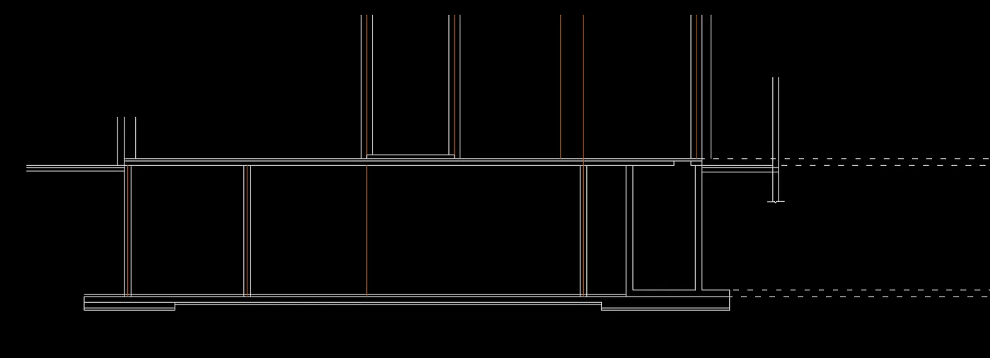
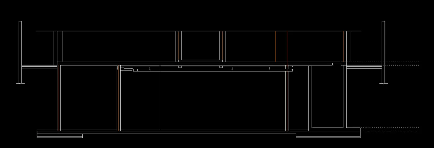
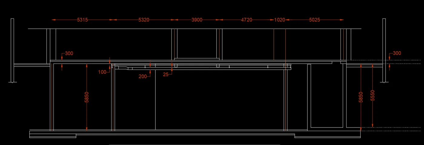
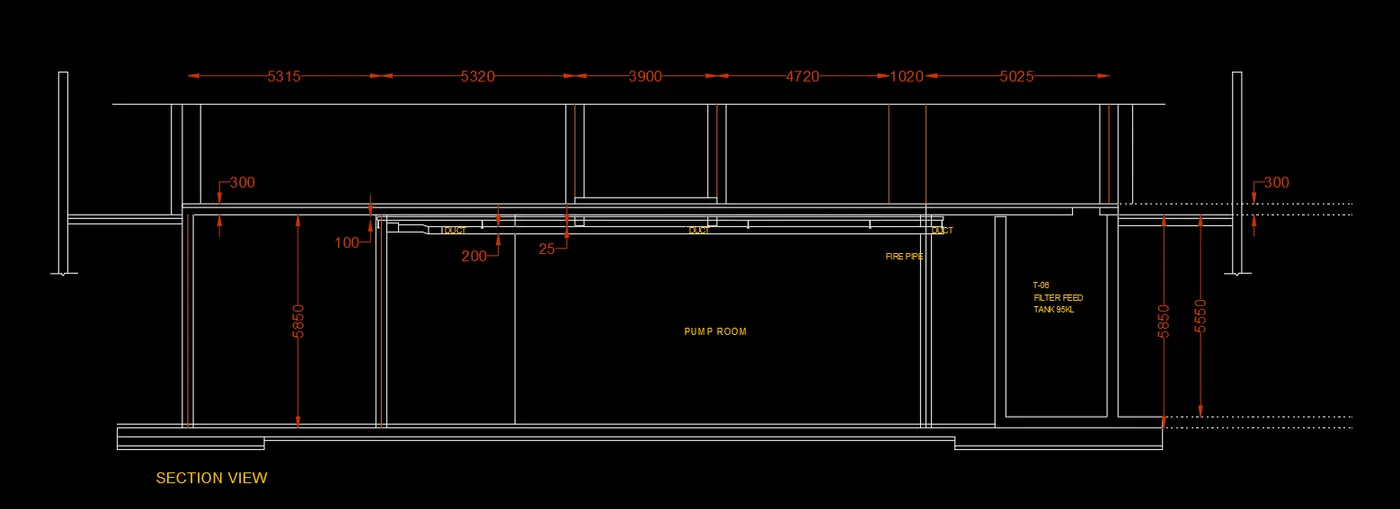
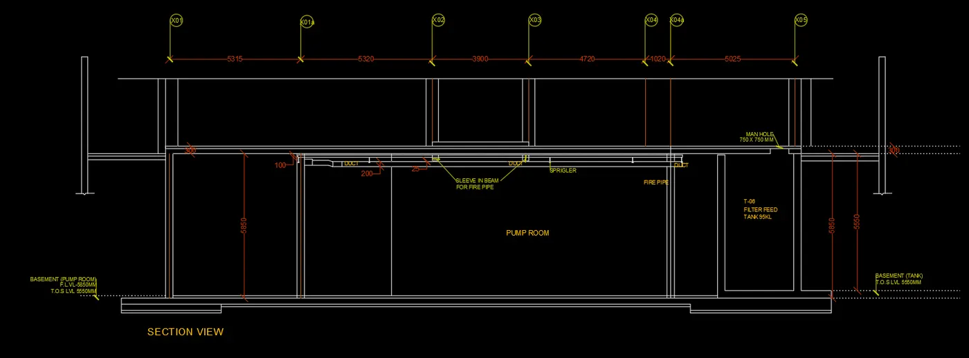
3.SECTION CREATION OF INDUSTRIAL BUILDING
PROCEDURE:
- Use command NEW ->Advanced Startup-> set the required units
- Or Set the required units using UNITS command.Here the unit system is Decimel
- Set the limit of the using LIMMAX command
- Various layers have been created using the LA command ex:0 Layer,Dimension Layer,Text Layer,Hatch Layer etc.Different colours can be given to each of these layers.
- XLINE command can be used to draw the infinte horizontal and vertical line
- Using the LINE command and the OFFSET command draw the required details
- As required use the COPY,TRIM,EXTEND,MIRROR,ERASE command
- HATCHING can be done wherever required by using the command h ->click on the OPTIONS button and select the required type of hatching pattern
- Do the dimensioning of the geometry using the DIMENSION command from the menu bar or using the DIMLINEAR command
- Continuation of the dimension can be done using the DIMCONTINUE command
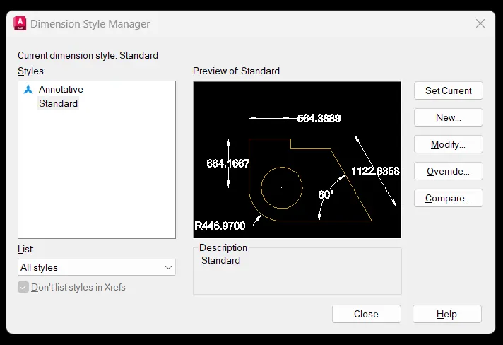
- For changing the dimensional style command D can be used
- From the RIBBON >Home>Text,the texting of the geometry can be done or by using the TEXT command
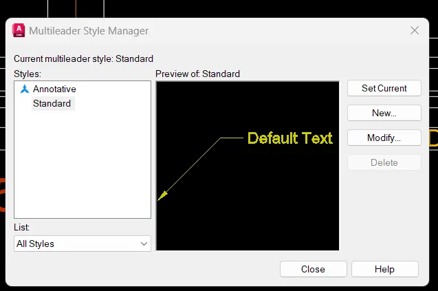
- From the RIBBON > ANNOTATE>MULTILEADER can be used wherever leaders are required
- After the completion of the drawing various layers can be assigned to the drawing