Creation of Multiple viewports, Scaling the drawing and setting in Template in AutoCad
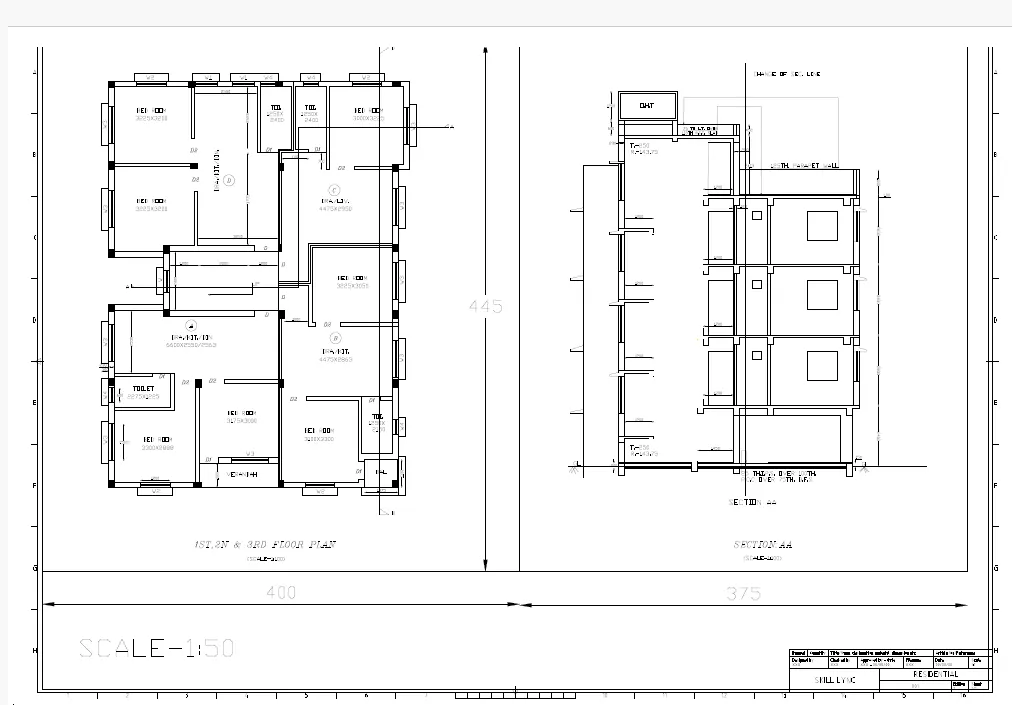
1. CREATION OF LAYOUT OF PLAN AND SECTION AA OF CHALLENGE 7 in ISO A1 LAYOUT
PROCEDURE:
- Take the AutoCAD drawing for which the layout has to be created
- Here we are creating the Layout for the challenge 7 drawing's plan and section
- Go to the layout option
- Rename the layout if required using the right click option
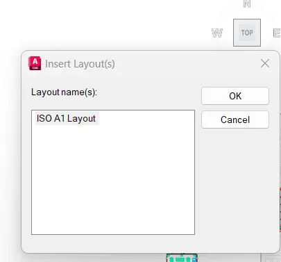
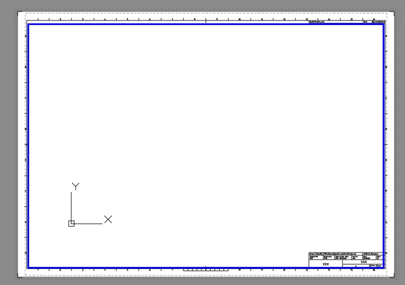
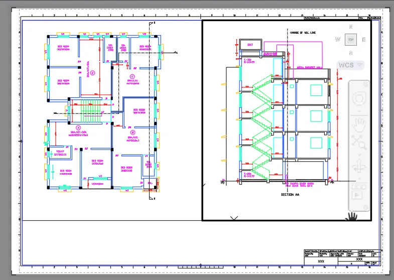
- Using the command LAYOUT ,select the TEMPLATE option ,from that select the Tutorial-mArch option,from that select the IS0 A1 Layout
- Now we can create the various views in the model for easy insertion of the required views in the created layout
- First set the model space to the required view.For example plan,section,elevation etc
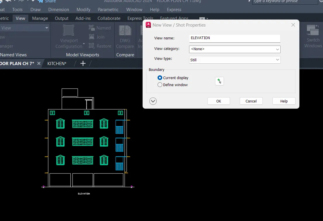
- From the RIBBON TAB,Go to the view option,From there select the new view option
- Create a new view for the plan,section,elevation etc
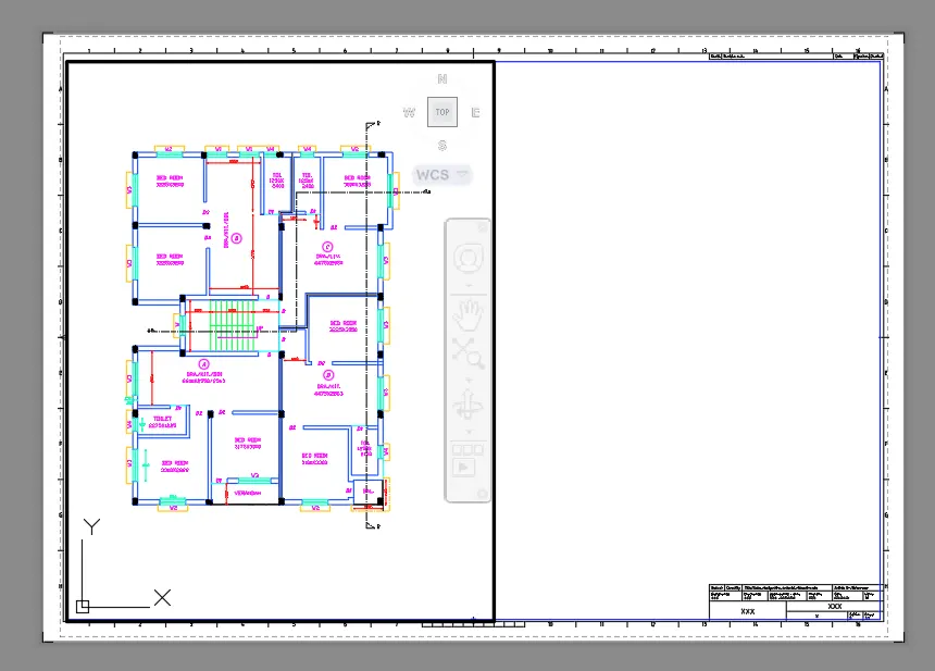
- Go to the ISO A1 layout ,Using the MV command draw the model view
- The required view can be set by selecting the MS SPACE and then the required view from the ribbon(plan,section,elevation etc which we have already created)
- Use the PS SPACE and MS SPACE commands to work on the paper and the model respectively
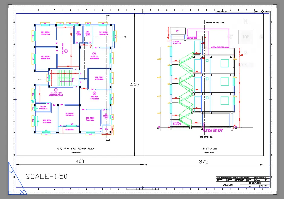
- The required scale can be provide to the views
- From the PS SPACE select the view and then right click ,go to the properties ,the scale of the view,locking of the display etc can be done
- TEXT command can be used for texting the geometry whevere required
- DIMLINEAR command can be used for the dimensioning of the layout size
- D command can be use for customizing the dimensional styles
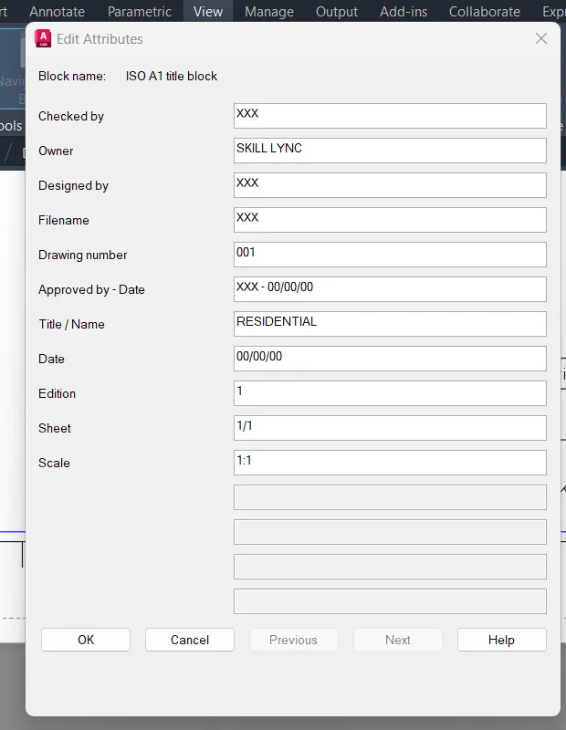
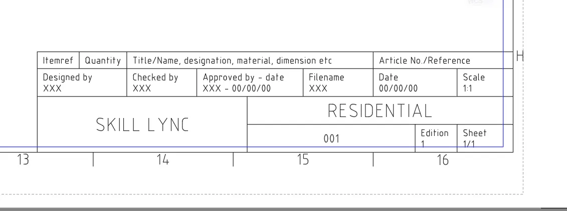
- For editing the standard template of IS0 A1,which has been made as a BLOCK can be done by using the ATTEDIT command
- The required new details can be entered into the template
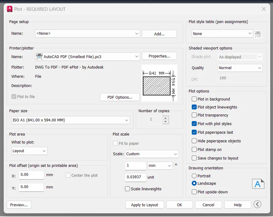
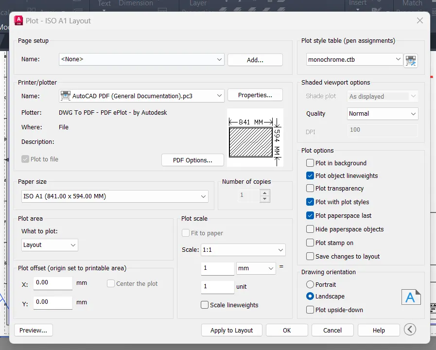
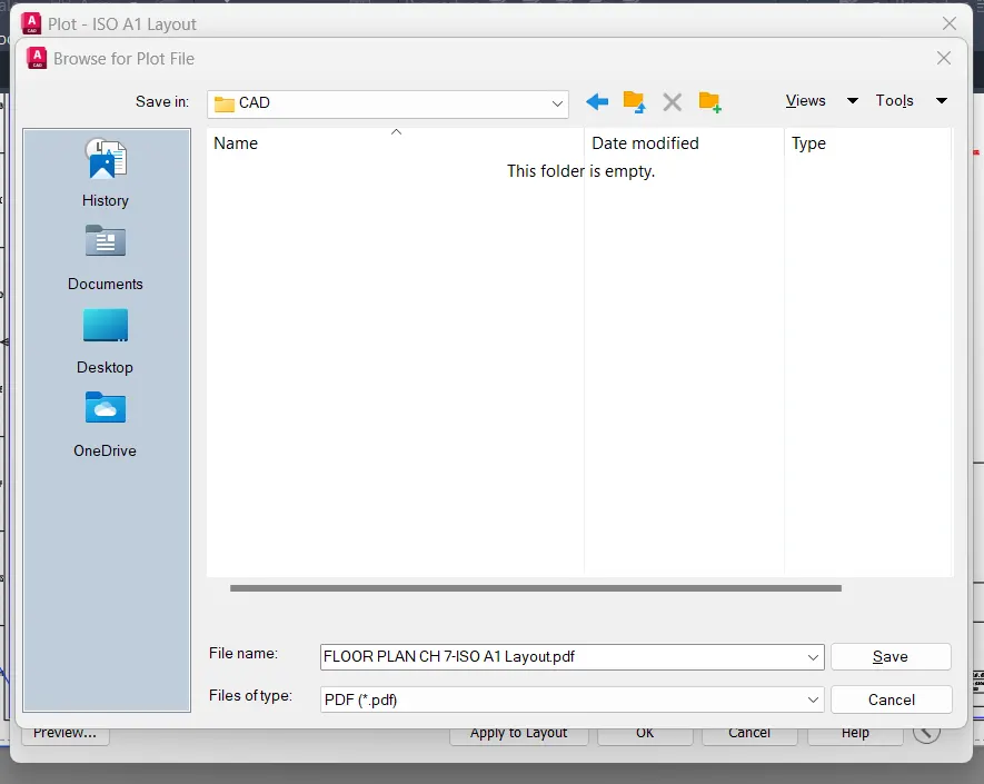
- For plotting the layot,use the command PLOT
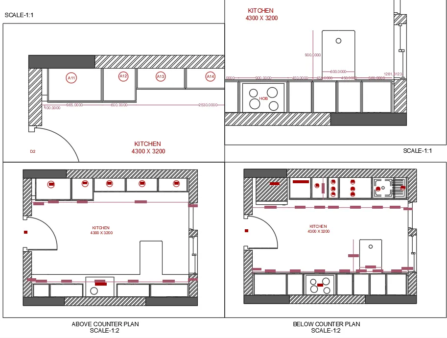
2. CREATION OF LAYOUT OF CHALLENGE 10 KITCHEN IN A4 SHEET
PROCEDURE:
- Take the AutoCAD drawing for which the layout has to be created
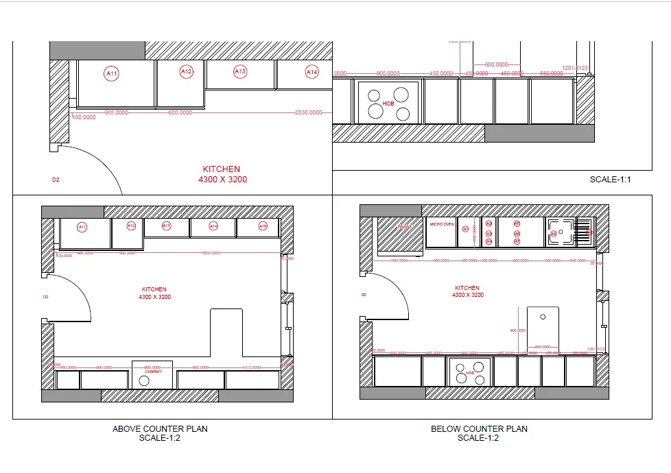
- Here we are creating the Layout for the challenge 10 KITCHEN
- Go to the layout option
- Rename the layout if required using the right click option
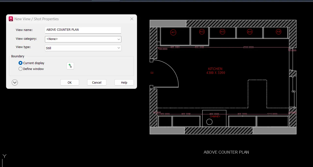
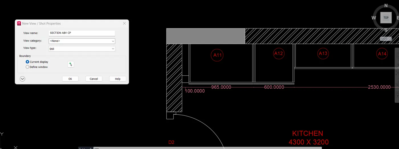
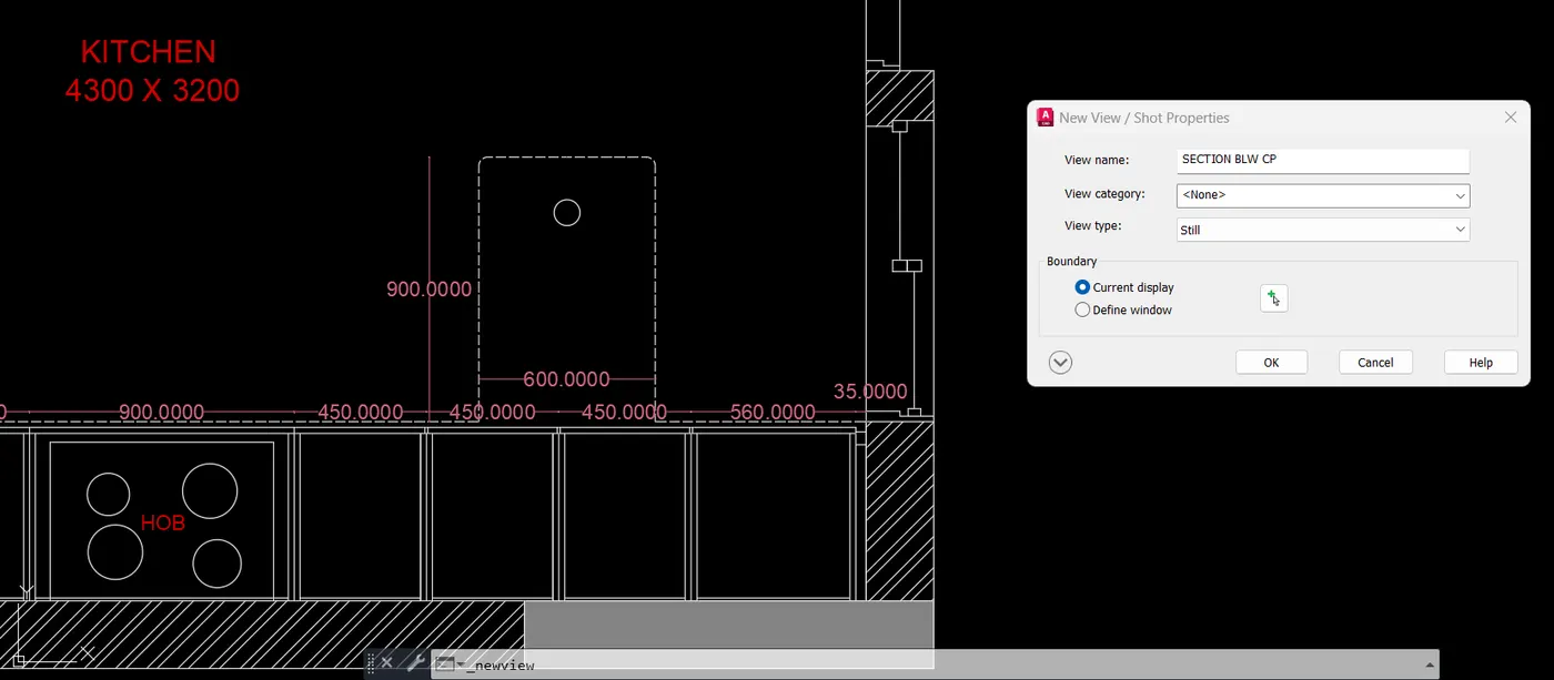
- Now we can create the various views in the model for easy insertion of the required views in the created layout
- First set the model space to the required view.For example Below counter plan,Above counter plan etc
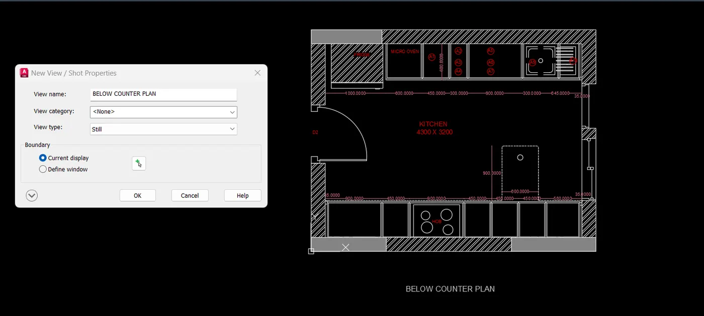
- From the RIBBON TAB,Go to the view option,From there select the new view option
- Create a new view for the Below counter plan,Above counter plan etc
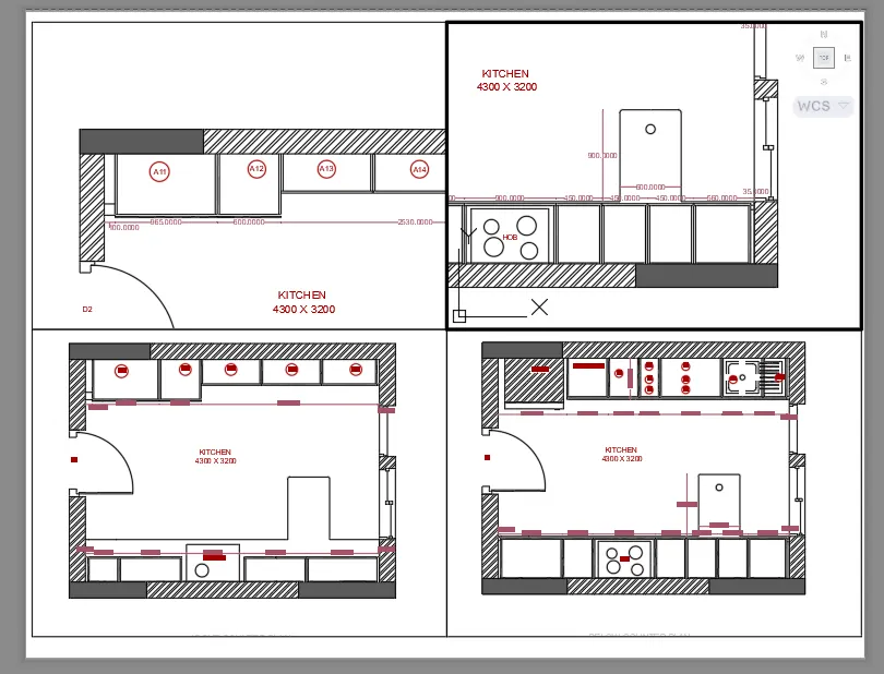
- Go to the layout ,Using the MV command draw the model view ( we can use either specify corner of view port option or LAyer 4 option)
- Then,the required multiple views can be set by the MV command and then selecting the MS SPACE and then the required view from the ribbon(Below counter plan,Above counter plan etc etc which we have already created )
- Use the PS SPACE and MS SPACE commands to work on the paper and the model respectively
- The required scale can be provide to the views
- From the PS SPACE select the view and then right click ,go to the properties ,the scale of the view,locking of the display etc can be done
- TEXT command can be used for texting the geometry whevere required
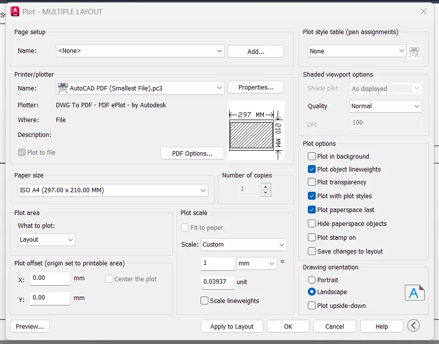
- For plotting the layot,use the command PLOT
- Here A4 paper size have been used for plotting
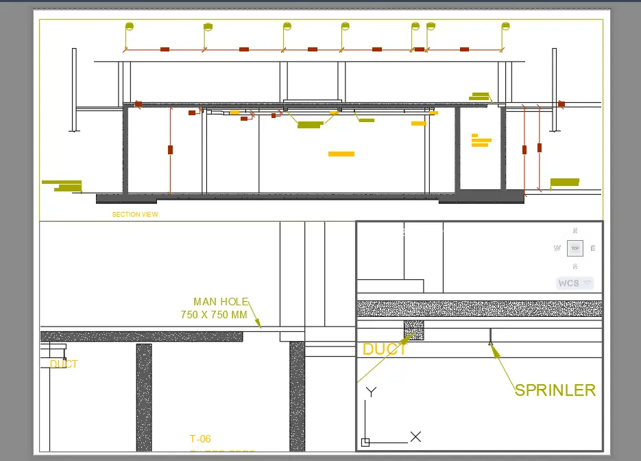
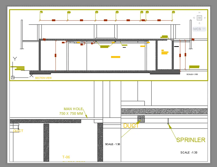
3. CREATION OF LAYOUT CHALLENGE 10 INDUSTRIAL BUILDING SECTION
PROCEDURE:
- Take the AutoCAD drawing for which the layout has to be created
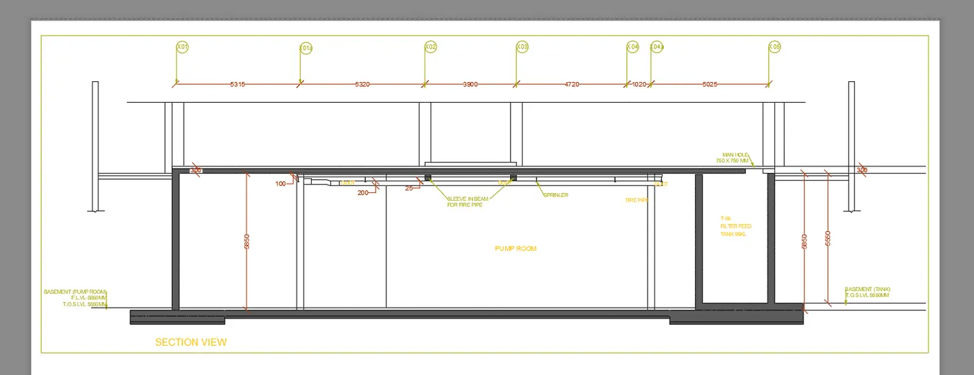
- Here we are creating the Layout for the challenge 10 sectional view
- Go to the layout option
- Rename the layout if required using the right click option
- Now we can create the various views in the model for easy insertion of the required views in the created layout
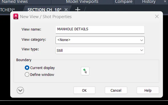
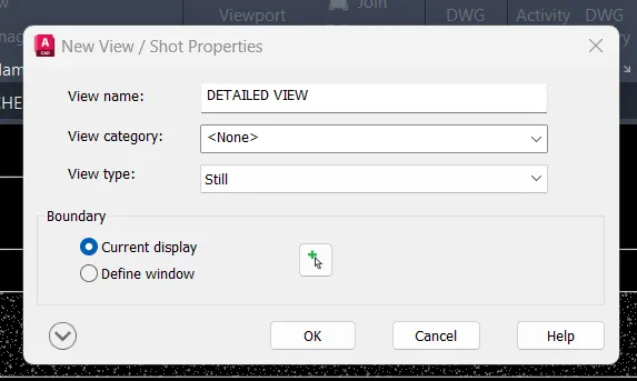
- First set the model space to the required view.For example Manhole details,Detailed view etc
- From the RIBBON TAB,Go to the view option,From there select the new view option
- Create a new view for the manhole details,detailed view etc
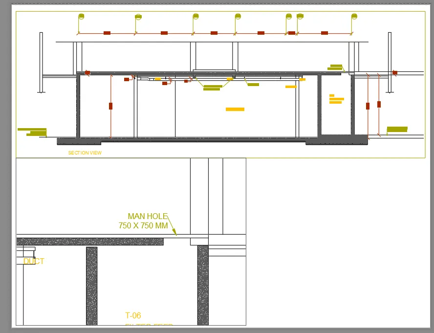
- Go to the layout ,Using the MV command draw the model view ( we can use either specify corner of view port option or LAyer 3 option)
- Then,the required multiple views can be set by the MV command and then selecting the MS SPACE and then the required view from the ribbon(manhole details,detailed view etc which we have already created)
- Use the PS SPACE and MS SPACE commands to work on the paper and the model respectively
- The required scale can be provide to the views
- From the PS SPACE select the view and then right click ,go to the properties ,the scale of the view,locking of the display etc can be done
- TEXT command can be used for texting the geometry whevere required
- For plotting the layot,use the command PLOT