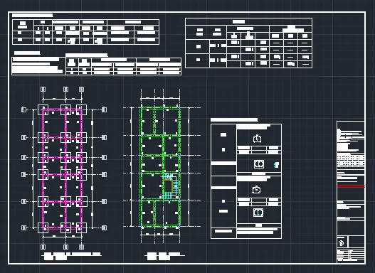
Project 1 _Creating an Architectural plan for the provided plot size and develop relevant basic structural drawings
AIM: TO DRAW AND DESIGN AND DRAFTING A RESIDENTIAL BUILDING .
OBJECTIVE: TO DRAW 1. ARCHITECTURAL DWG
2. STRUCTURAL DWG.
OF A 60' X 20' PLOT SIZE RESIDENTIAL HOUSE USING DIFERENT KIND OF DRAFTING TOOLS IN AUTOCAD SOFTWARE.
Procedure:
Their are various kind of commands are used, these are as below:-
- QNEW COMMAND
- UN COMMAND
- D 'ENTER'
- LINE COMMAND
- TRIM COMMAND
- 'ARC' COMMAND.
- EXTEND COMMAND
- XL COMMAND
- MTEXT & DT COMMAND.
- BLOCK COMMAND
- COPY COMMAND
- OFFSET COMMAND
- FILLET COMMAND
- PL COMMAND
- HATCH COMMAND
- DIM 'ENTER'
- DIMCON 'ENTER'
- C 'ENTER'
- REC 'ENTER'.............ETC.
ARCHITERCTURAL DWG:
STEP:-1
- First go to new dwg file using QNEW 'Enter' command.
- Then setup the unit using UN 'Enter' command.
- now set the dimension 'Architectural' using 'D' enter command.
STEP:-2
- creat a rectangel of 20' length and 60' width. [using 'line' Command]
- Type O in command box, press enter, specify offset distance as 10" units and take offset to lines in inner sides.
- Type O in command box, specify offset distance 12' units, press enter and take offset to inner vertical line in left direction.
- Type O in command box, specify offset distance 5" units, press enter and take offset to inner vertical line in left direction.
- Type O in command box, specify offset distance 13' units, press enter and take offset to inner horizontal line in downward direction in upside.
- Type O in command box, specify offset distance 5" units, press enter and take offset to inner horizontal line in downward direction in upside.
- Type O in command box, specify offset distance 12' units, press enter and take offset to inner horizontal line in upward direction in downside.
- Type O in command box, specify offset distance 5" units, press enter and take offset to inner horizontal line in upward direction in downside.
- Type O in command box, specify offset distance 8' units, press enter and take offset to inner horizontal line in downward direction in upside.
- Type O in command box, specify offset distance 5" units, press enter and take offset to inner horizontal line in upward direction in downside.
- now using 'TR' & 'F' command trime the extra part and fillet the corner.
- now take 9'-6" offset from upside 12' offset. then 5" offset.
- take offset of 7' towards leftside , then 5" offset.
- using offset command creat the stair case by taking 10" offset from first stair line.
- now using line and arch command creat door plan block.
- and window plan block using rectangal and line column.
- now using MTEXT and DT COMMAND add the text.
- now creat different size door window block using block command.
- using line command add a 5' wide porch area in the entrance.
RESULT:
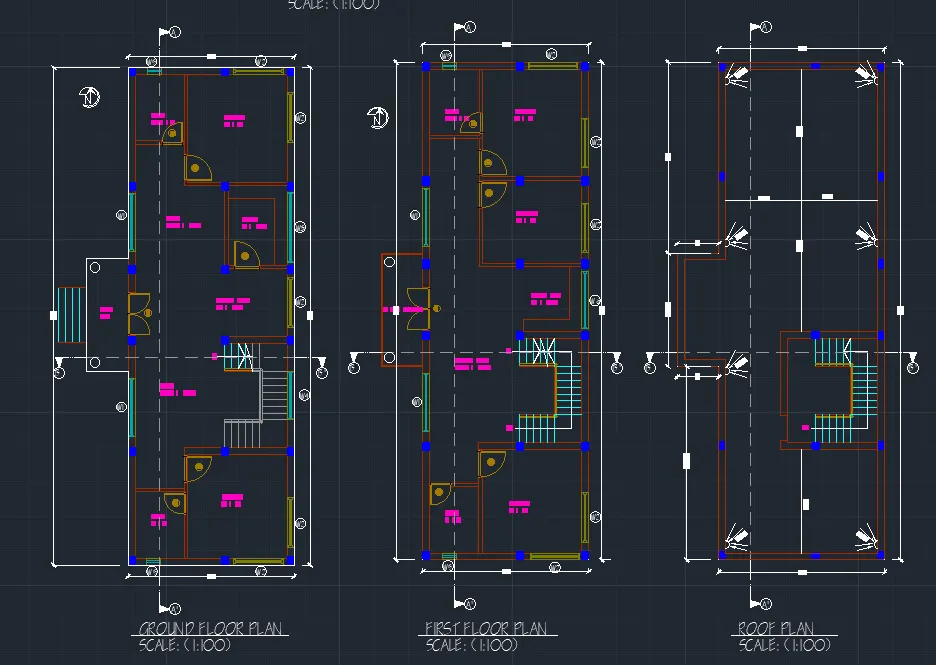
STEP-2:
- For section elevation using 'XL' command, draw the ray line. from plan .
- take offset of required distance by using offset command in the command box.
- Then make the section of staircase using 'XL' command and 'trim' and extend command also.
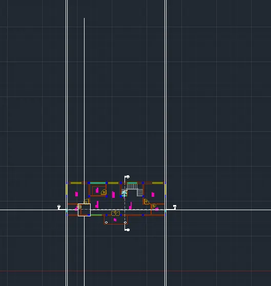
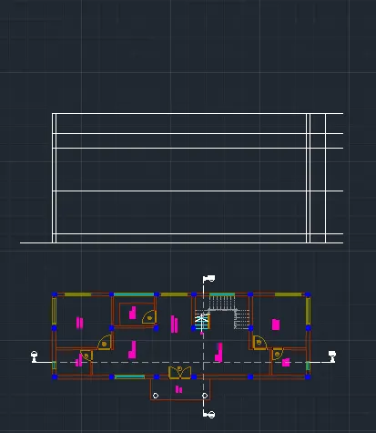
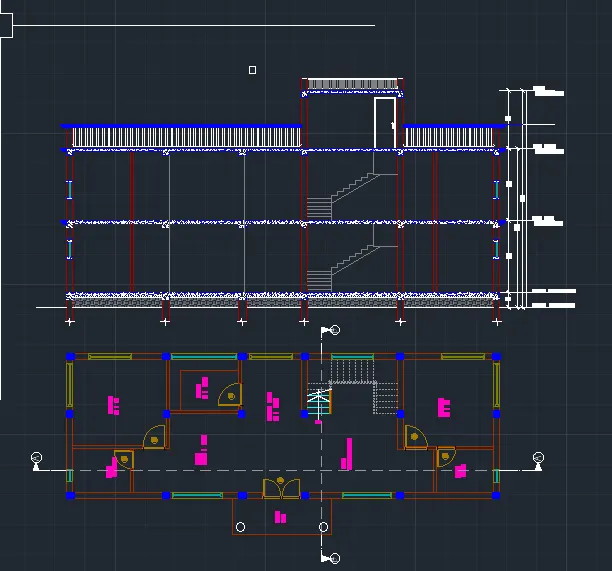
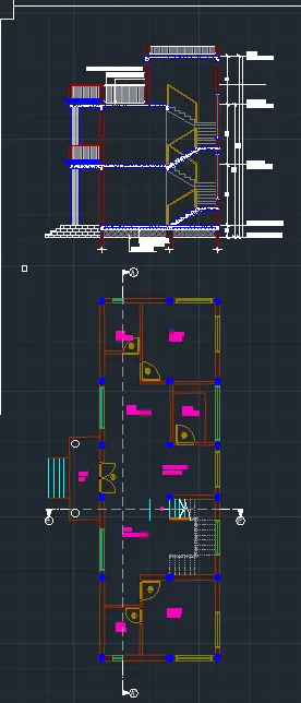
RESULT:
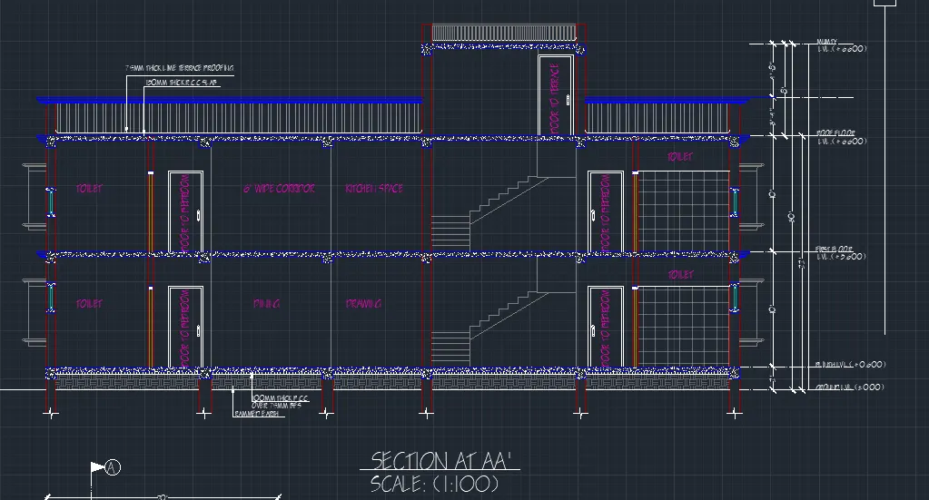
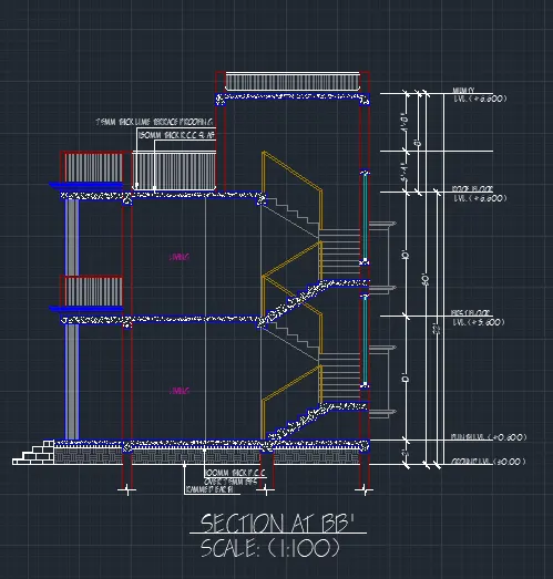
STEP-3:
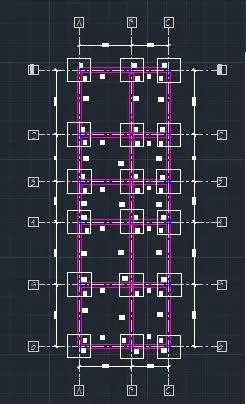
- Now for structural drawing make a rectengale of 250 X 300 for column size. put them in the required place of the plan.
- then take a copy of the columns as a block .
- now using 'XL' command make the centerlines
- using dim give the required dimension as shown in the DWG.
- using text command 'DT' command give the tia beam name and column name, and footing name.
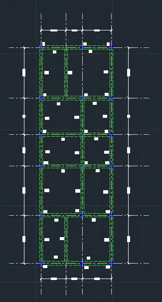
- now using the same process make the floor beam layout as per given DWG.
Here are the screenshot of the process:
RESULT:
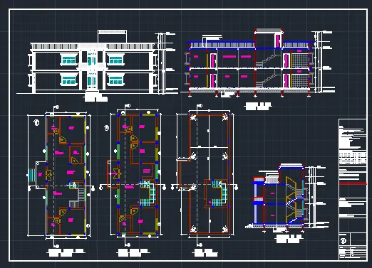
HERE ARE THE FINAL RESULT OF THE PROJECT.
- ARCHITECTURAL DWG.
2. STRUCTURAL DWG.