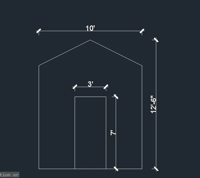
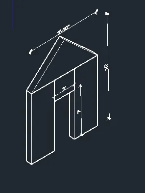
Creating various 3D Models like Furniture, Footing, Girder, Column drop with panel and Gable Wall in AutoCad
Using AutoCad to create a variety of 3D models, including furniture, footing, girders, column drops with panels, and gable walls
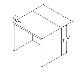
1. Aim:- To generate a 3D furniture component, as depicted in Figure.
Procedure:-
- To launch the AutoCAD application, click on it.
- In the command bar, type QNEW, then press
- Choose Imperial as the default option.
- Click "Use a Wizard" in the default configuration. In the advanced setting, select "Architectural" and "0'0" for precision. Press "Next."
- Click Next after setting Angle to Decimal Degree and Precision to 0.
- Press NEXT after setting Angle Measure to EAST.
- Press NEXT after selecting Counter-Clockwise as the Angle Direction.
- Length and width should be entered to set the area to 50 feet.
- Click "finish."
- Hold ortho, turn on object snap
- Hold off on using Snap and Grid.
- To scale the inserted content, choose Inches and Un+enter Type > Architectural, Precision > 0'0" Units.
- Go ahead and
- Choose Workspace Switching >. 3D Modelling
- Choose Visual Style Control > Two-dimensional wireframe
- Consider using the 3D Orbit command.
- Choose a view, such the UCS direction, which is displayed below.
- create a rectangel of size 3'X 2'
- now using extrude command extrud the rectange upto 2'-6".
- now using "SOLID EDIT" command choose "BODY" option.
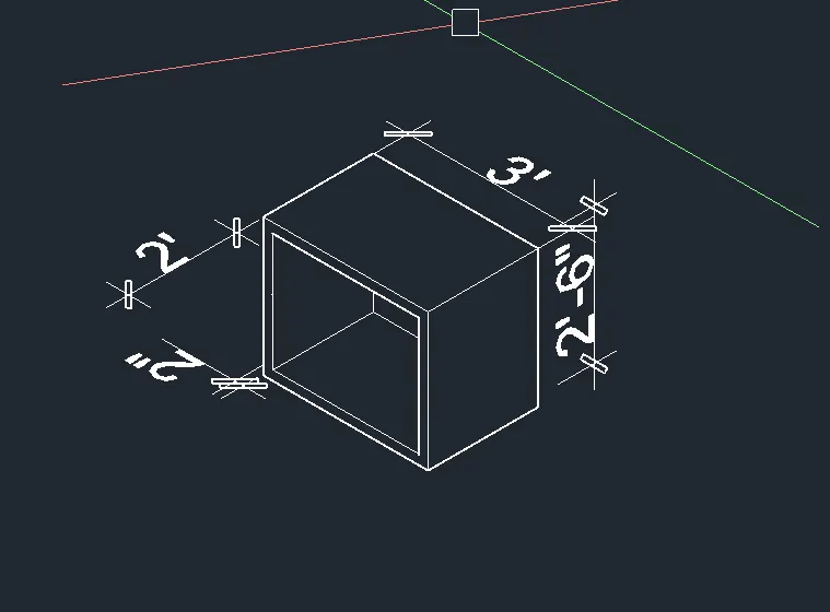
- and using shell make a shall in side the solid's body.
As a result the following dwg get ready.
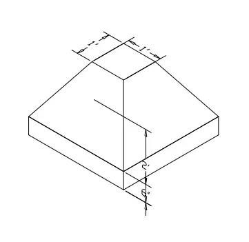
2. Create the 3d Model of an Isolated footing as shown in Figure.
Procedure:-
- To launch the AutoCAD application, click on it.
- In the command bar, type QNEW, then press
- Choose Imperial as the default option.
- Click "Use a Wizard" in the default configuration. In the advanced setting, select "Architectural" and "0'0" for precision. Then, push Next
- Click Next after setting Angle to Decimal Degree and Precision to 0.
- Press NEXT after setting Angle Measure to EAST.
- Press NEXT after selecting Counter-Clockwise as the Angle Direction.
- Set Area by entering 5' for both Length and Width.
- Click "finish."
- Hold ortho, turn on object snap
- Hold on to Grid and Snap > Off Un+enter Type > Architectural, Accuracy > 0'0" Units to Scale Inches for Inserted Content
- Go ahead and
- Choose Workspace Switching >. 3D Modelling
- Choose Visual Style Control > Two-dimensional wireframe
- Consider using the 3D Orbit command.
- Draw a rectengle of 3'X3'
- now extrude the rectangle upto 6".
- then using "Solid Edit" choose face Extrude
- then in extrude command choose extrude angle 23 degree.
- now choose new ucs and give the dimensions.
As a Result the below dwg created.

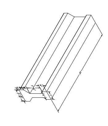
3.Create the 3D view of the AASTHO Type Girder.
Procedure:-
- To launch the AutoCAD application, click on it.
- In the command bar, type QNEW, then press
- Choose Imperial as the default option.
- Click "Use a Wizard" in the default configuration. In the advanced setting, select "Architectural" and "0'0" for precision. Then, push Next
- Click Next after setting Angle to Decimal Degree and Precision to 0.
- Press NEXT after setting Angle Measure to EAST.
- Press NEXT after selecting Counter-Clockwise as the Angle Direction.
- Length and width should be entered to set the area to 50 feet.
- Click "finish."
- Hold ortho, turn on object snap
- Hold on to Grid and Snap > To scale added text, select Inches under Units. Off Un+enter Type > Architectural, Precision > 0'0"
- Go ahead and
- Choose Workspace Switching > 3D Modelling
- Choose Visual Style Control > Two-dimensional wireframe
- Choose View Control > top
- now create the plan of above picture using 2d drafting.
- then using 3d drafting tools extrude the polyline.
- upto 10'.
As a result the following DWG created.
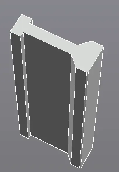
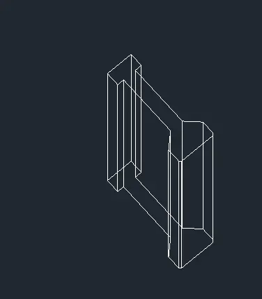
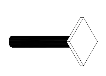
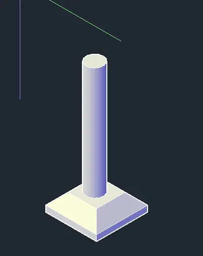
4.Create a 3d Model of a drop column with panel as shown in section and isometric view.
Procedure:-
- To launch the AutoCAD application, click on it.
- In the command bar, type QNEW, then press
- Choose Imperial as the default option.
- Click "Use a Wizard" in the default configuration. In the advanced setting, select "Architectural" and "0'0" for precision. Then, push Next
- Click Next after setting Angle to Decimal Degree and Precision to 0.
- Press NEXT after setting Angle Measure to EAST.
- Press NEXT after selecting Counter-Clockwise as the Angle Direction.
- Length and width should be entered to set the area to 50 feet.
- Click "finish."
- Hold ortho, turn on object snap
- Hold on to Grid and Snap > To scale added text, select Inches under Units. Off Un+enter Type > Architectural, Precision > 0'0"
- Go ahead and
- Choose Workspace Switching > 3D Modelling.
- Choose Visual Style Control > Two-dimensional wireframe
- Choose View Control > top.
- now creat the plan of above column.
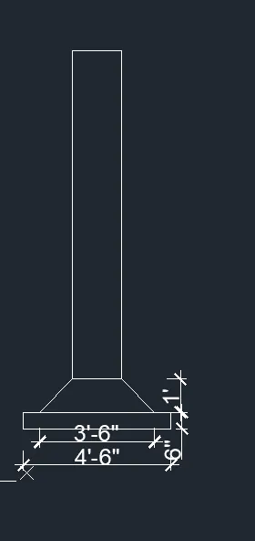
- now creat the base of the column.
- And extrude the column as required length.
As a result the below picture created.
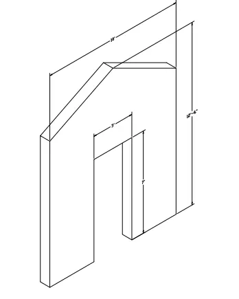
5. Create the 3d model of a wall as shown in Figure. Consider wall thickness as 9".
Procedure:-
- following the above procedure.
- creat the plan of the wall in 2d wireframe.
- now in 3d modeling tools draw the wall ployline.
- and extrude these polynile upto required lentgh.
As a result the following dwg created.