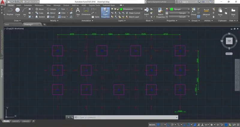
Project 1 _Creating an Architectural plan for the provided plot size and develop relevant basic structural drawings
AIM:
To create an architectural plan for the provided plot size and develop relevant basic structural drawings.
INTRODUCTION:
- Plans are 2D diagrams used to describe the buildings dimensions and other details.
- Elevation of a building shows the front view.
- Section drawing shows how the building would look if the given sectional line cuts through the buiding.
- Column layout is used to represent the location of the columns along with their dimensions.
- Beam layout is used to represent the location of the column with the length and the cross section.
- Footing layout represents the placement of the footing in the plot.
PROCEDURE:
STEP 1:
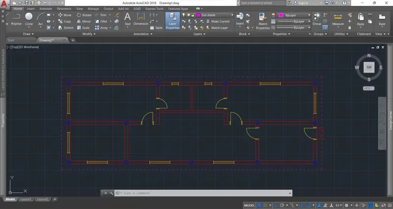
The different layers are created and assigned to different feature, then walls layer is selected to draw the rooms and walls.
STEP 2: Drawing the Plan
Xline command was used to draw vertical and horizontal lines.
Offset command is used to create walls and other rooms by offsetting the lines according to the needed dimensions.
Trim command is used to trim the excess unwanted lines from the offsetted lines.
Delete command is used to remove the unwanted lines from the drawing that cannot be trimmed.
Extend command is used to lengthen the line in the needed direction.
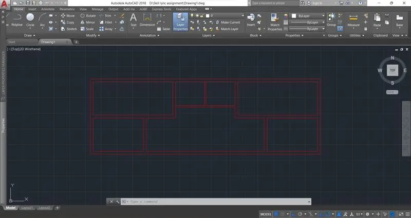
Once the walls and rooms are drawn, then change the layer to columns.
Create a column using rectangle command, and then Hatch it.
Make this column into a block by using the create block from insert menu.
Using Copy command, make multiple copies of this column and paste it in the needed locations.
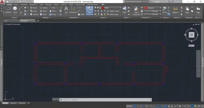
Then change the layer to Windows. Then create window and make them into blocks. Then copy paste them in their locations.
Then change the layer to Doors. Then create door and make them into blocks. Then copy paste them in their locations.
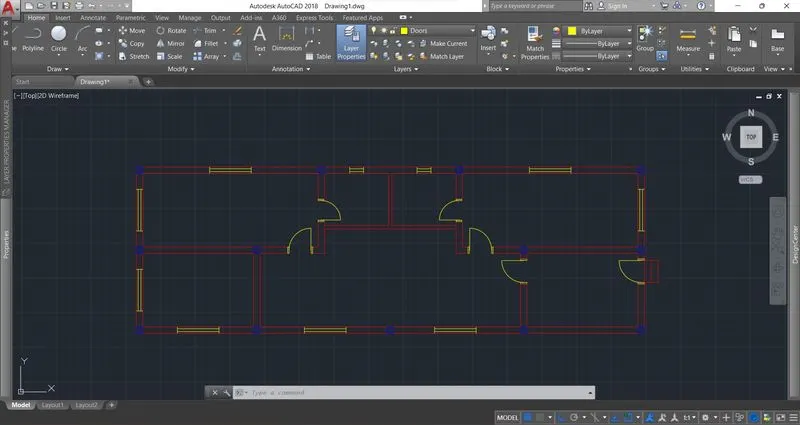
Now change the layers to projection, and the draw the window shades by projecting 450mm from the walls.
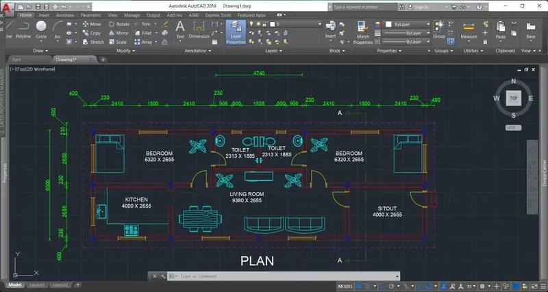
Now change the layers to text and using mtext command enter the room names and their dimensions on the appropriate locations. Also by using the properties option we can increase the text size if needed.
Now change the layers to dimension, and then start to mark the dimension on the plan. Also use the dimcontinue command to draw dimensions that are in series to each other.
Now change the layers to section line and start to draw the section line by using line command. Then change the linetype to the desired type.
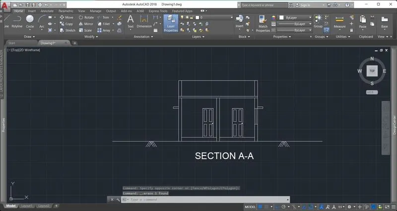
STEP 3: Drawing Section
Xline command is used to draw vertical lines from the points that crosses the section line and which will be seen from the sectional view.
Using trim command, remove the unwanted lines from the drawing.
Using Offset command, create the floor levels.
The section view A-A is created by this way.
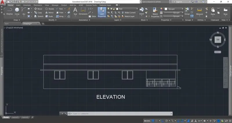
STEP 4: Drawing Elevation
Xline command is used to draw vertical lines from the end points of the wall and windows that are visible in the elevation.
Using trim command, remove the unwanted lines from the drawing.
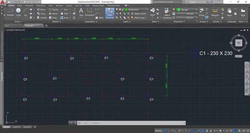
STEP 5: Drawing Column Layout
Column layout is obtained by turning off all the layers, and then turning on only the column layer.
Then the column layer is copied and placed in a different location.
Then the dimensions of the column and the numbering is given.
STEP 6: Drawing Beam layout
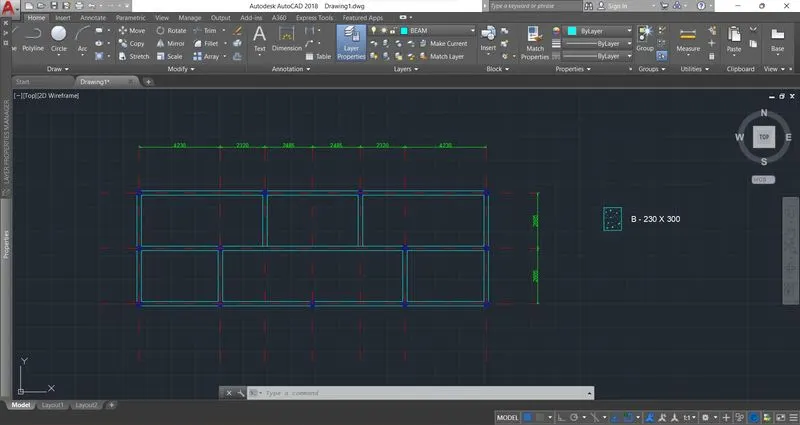
Beam layout is obtained by drawing the beams over the column layout that rests on the column.
Then the beam numbering and cross section is also given.
STEP 7: Drawing Footing layout
Footing layout is drawn over the column layout by creating a footing plan for a single column and then pasting it over all the columns.