Creation of Multiple viewports, Scaling the drawing and setting in Template in AutoCad
AIM :
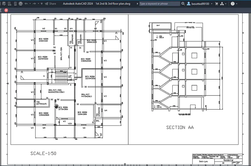
1. Create a layout of the Plan and Section A of the project in Challenges 7, using the template Tutorial-mArch.dwt in a scale as given in the Figure
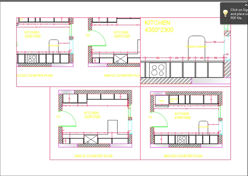
2. Create a layout of the Kitchen drawn in Challenge 9 as shown in Figure
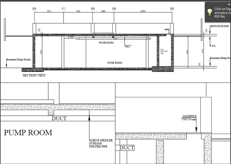
3. Create a layout of the section created in Challenges 9
INTRODUCTION :
A viewport is a window created in a Paperspace layout that displays the information generated in the Modelspace to a specified scale. A layout can have multiple viewports of different shapes.
There are two types of AutoCAD Viewports:
- Model Space viewport
- Layout viewport
Command-line: To start the Viewport tool from the command line, type “MV” and press [Enter].
Layers can be turned on and off and displayed differently in individual viewports. Once a viewport is activated, from the Ribbon Home tab > Layers panel click the Layer Properties button. In addition to the usual properties (See module 03-Drawing Organisation for further details on Layer properties). The following properties are available and control the individual viewports appearance.
- VP Freeze controls the appearance of a Layer in the activated viewport.
- VP Color allows you to override the printed colour of elements drawn on this layer for the activated viewport. This can be especially important if using CTBs in order to get elements to print different values between viewports.
- VP Linetype overrides the plotted Linetype of elements drawn on this layer for the activated viewport.
- VP Lineweight overrides the plotted Lineweight of elements drawn on this layer for the activated viewport.
- VP Transparency overrides the plotted transparency of elements drawn on this Layer for the activated viewport.
- VP Plot Style overrides the style applied to the layer in the activated viewport.
PROCEDURE :
1. Step by Step procedure of layout of the Plan and Section A of the project in Challenges 7, using the template Tutorial-mArch.dwt in a scale as given in the Figure
- Open a old file: Challenge 7
- Open Layout
- Click on the right side of mouse & select Template
- Select Tutorial -mArch
- Click on the right side of mouse & select Page Setup Manager
- Than Name DWG to PDF
- Paper size ISO A1 (594.00 X 841.00 MM)
- Select Plot style Table as Monochrome
- Enter (MV) : MView Command
- In the Layer View Select 2 [Enter]
- Enter (MS) : Model Sheet Command
- Enter (PS) : Paper Sheet Command
- In the Model Space
- Enter (V) : View Command
- Create a new view according to the scale 1:50
- Enter (MT) : Multi Text Command
- Complete layout of the Plan and Section A of the project in Challenges 7
2. Step by Step procedure of layout of the Kitchen drawn in Challenge 9 as shown in Figure
- Open a old file: Challenge 9
- Open Layout
- Click on the right side of mouse & select Page Setup Manager
- Than Name DWG to PDF
- Paper size ISO A4 (297.00 X 210.00 MM)
- Select Plot style Table as Monochrome
- Enter (MV) : MView Command
- In the Layer View Select 2 [Enter]
- Enter (MS) : Model Sheet Command
- Enter (PS) : Paper Sheet Command
- In the Model Space
- Enter (V) : View Command
- Create a new view according to the scale 1:2 ; 1:1
- Enter (MT) : Multi Text Command
- Complete layout of the Kitchen drawn in Challenge 9
3. Step by Step procedure of layout of the section of Industrial Building created in Challenges 9
- Open a old file: Challenge 9
- Open Layout
- Click on the right side of mouse & select Page Setup Manager
- Than Name DWG to PDF
- Paper size ISO A3 (420.00 X 297.00 MM)
- Select Plot style Table as Monochrome
- Enter (MV) : MView Command
- In the Layer View Select 2 [Enter]
- Enter (MS) : Model Sheet Command
- Enter (PS) : Paper Sheet Command
- In the Model Space
- Enter (V) : View Command
- Create a new view according to the scale 1:30 ; 1:100
- Enter (MT) : Multi Text Command
- Complete layout of the section of Industrial Building created in Challenges 9
RESULT :
1. A layout of the Plan and Section A of the project in Challenges 7, using the template Tutorial-mArch.dwt in a scale as given in the Figure
2. A layout of the Kitchen drawn in Challenge 9 as shown in Figure
3. A layout of the section created in Challenges 9