Project 1 _Creating an Architectural plan for the provided plot size and develop relevant basic structural drawings
WEEK 8 CHALLANGE REPORT ACAD SKILL LYNC
-
Aim is to design and draft the layout of a Residential Building with a plot size of 60’x20’ and orientation facing East.
Is required to develop the following:
1.Architectural Drawing (Floor Plan, Elevation and Sections)
2.Structural Drawing (Column, Beam and Footing Plan)
Important is to use the proper drafting tools and use proper text styles and dimension methods to document it.
-
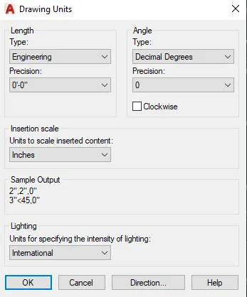
First thing I do is I open a new page and set uo the units using Command:Units
-
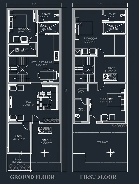
After doing my research I deside to go with the layout of a residencial building of size 60’x20’ facing East as shown in the figure.
-
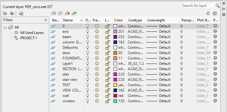
I continue by creating Layers which I will use for the entire Project.
-
Now I start to sketch the Architectural Drawing (Floor Plan, Elevation and Sections)
First is the Floor Plan of Ground Floor and First Floor.
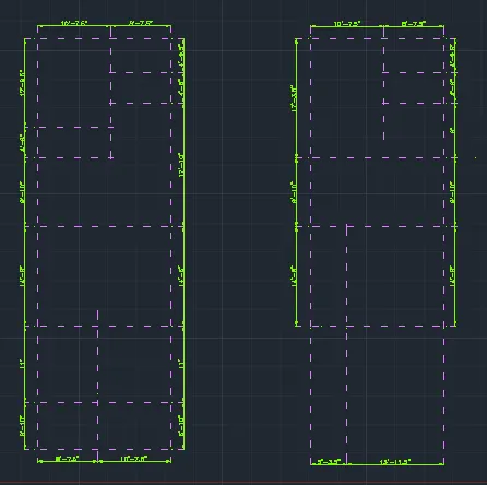
To do so I start sketching the axis where the walls and column will be placed. I use Commands: Line and Offset and layer Axis..
-
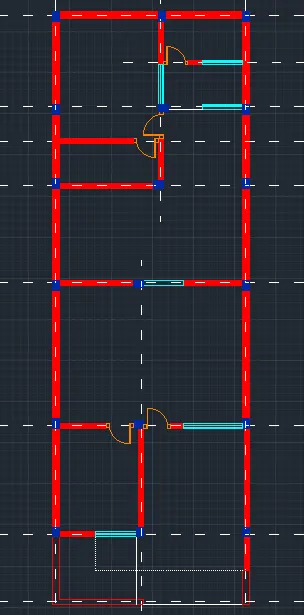
Then I start Sketching the walls using Command Offset and Layer wall. Interior walls 6’ thick and Exterior walls 9’ thick.

-
Using Commands: Trim, Line, Fillet I create the walls with layer wall, and I create the columns as well using layer column.
-
Next using layer door I create the doors and with layer window I create the windows using commands: line, circle, trim…After I Hatch the walls and columns using Hatch pttern Solid and colour as their particular layers.
-
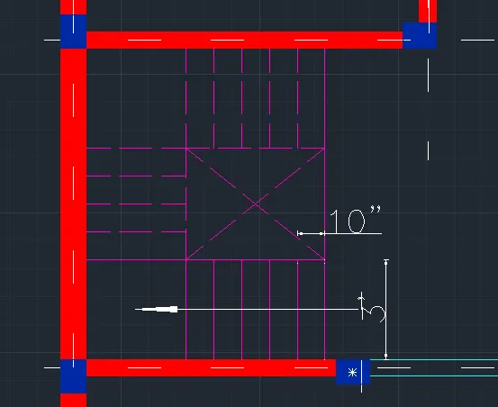
I sketch the stairs using layer Stair and Stair view and using command: line, offset or copy with option array and fit.
-
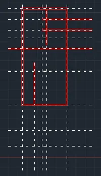
The same commands and steps I follow to sketch the First Floor Plan.
-
Now I create one Text Style, and one Dimmension style in order to provide the nesesary text and dimensions.
Text Style for the Text and dimensions of the plan
Command: STYLE> Standard>font name: romans.shx
height: 7’’
Dimmension Style
Ribbon> Annotate> Dimensions>ISO-25>Modify>
>Lines: √ Fixed length extension lines
Length: 1’’
>Simbol and Arrows
Arrow size 7.5’’
>Text Style Standart
>Text Alignment Alignet with dimension line
>Text placement Centered
>Unit Format Engineering
>Precision 0’-0.0’’ ok
-
Using the comands from the ribbon:
Annotate>Text>Standard Text Style>Single line or Multiline
Annotate>Dimensions>Standart Style>Dimension
Standart Style>Continue
-
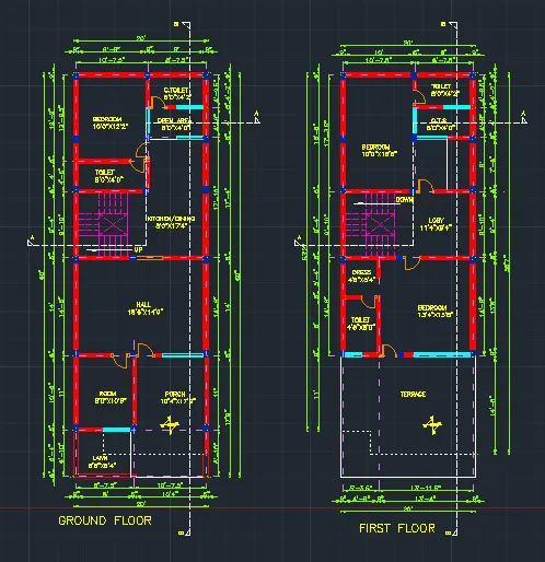
After using the above commands and layers, alongside with the text and dimensioning this is the final sketch of Ground Floor and First Floor.
-
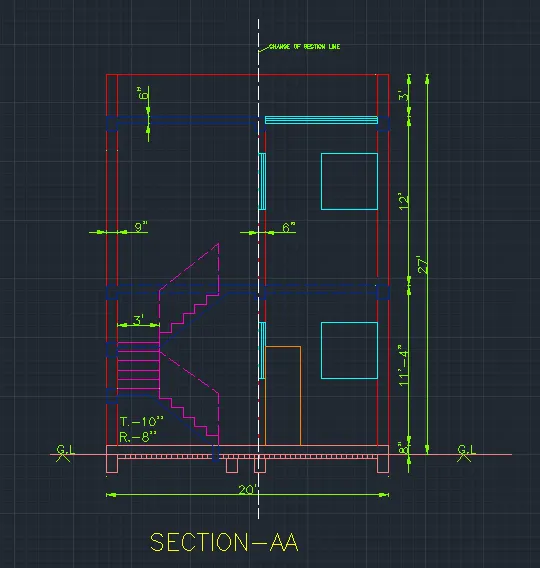
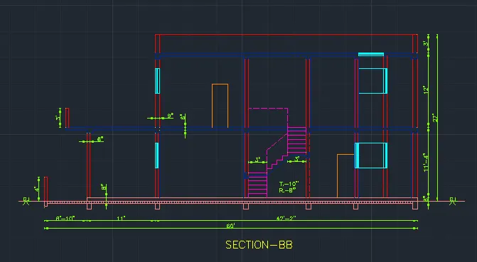
To Create Section AA and Section BB. I copy and rotate with 90 degree the Ground Floor and First Floor Plan and draw Ray lines using Command: Ray from the plans to the space where I will draw the section.
I use layers wall, column,stair, stair view, door window and commands Line, Trim, Offset, Copy, Rectangular… to sketch the elements of the section as shown. I use hight of slab 6’’, Tread of stairs 10’’, rise of stairs 8’’, high of plinth 8’’, high of windows 4’ and high of doors 7’. High of one floor is 12’. the ground floor have a plinth high of 8’’ and 11’4’’ high of the floor.
-
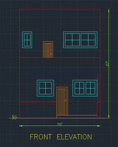
Same steps I follow to sketch the Front elevation of the Residential Building.
2.Structural Drawing (Column, Beam and Footing Plan)
-
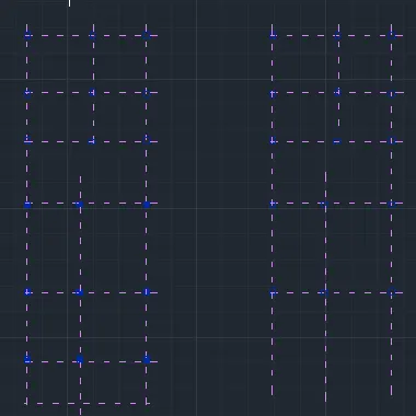
To sketch the Column and Footing Plan I turn off all layers exept Axis and Column layers.
I copy the layout as shown in the figure.
-
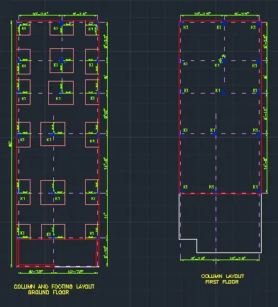
Using layer Foundation and commands Offset and Fillet I create the Footing on each column of the Ground Floor.
Columns are of size K1: 9’’X12’’.
Footing is 2’6’’wide from each side of the column as shown.
In the First floor I sketch the Column Layout as shown using Text and Dimensioning where required.
I create another Text Style and Dimension style for the dimensioning of the footing.
Text Style for the dimensions of the footing.
Command: STYLE> New>Style1>font name: romans.shx
height: 3’’
Dimmension Style
Ribbon> Annotate> Dimensions>ISO-25>Modify>
>Lines: √ Fixed length extension lines
Length: 1’’
>Simbol and Arrows
Arrow size 7.5’’
>Text Style Style1
>Text Alignment Alignet with dimension line
>Text placement Centered
>Unit Format Engineering
>Precision 0’-0.0’’ ok
-
After using the above commands and layers, alongside with the text and dimensioning this is the final sketch of Column and Footing Layout Ground Floor and Column Layout First Floor.
-
To sketch the Beam Layout I do the same step as with column and footing layout. I turn off all layers exept Axis and Column layers.
I copy the layout as shown in the figure.
-
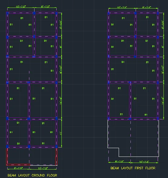
Using layer Beam and commands: Line,Offset, trim I sketch the beams of the layout. The beam dimensions are B1: 9’’x12’’.
-
After using the Text and Dimensioning Commands this is the final look of the Beam Layout of the Ground and First Floor.
-
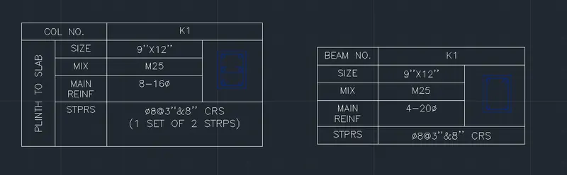
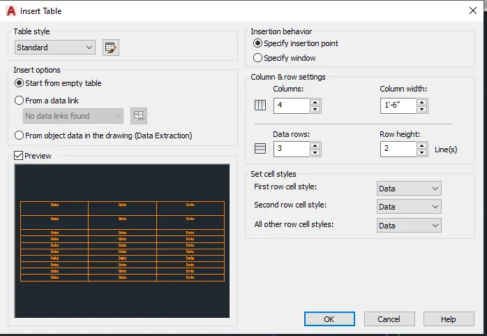
Last thing I do is creating a table for the Column details, and a table for the Beam details,
I create both tabls with same dimensions, the Beam Table has 1
column less.
I Create a text style for the table
Text Style for the tables.
Command: STYLE> New>Style2>font name: romans.shx
height: 2’’
Using Command from Ribbon: Annotate>Tables>Table
-
I fill in the columns with the details as shown and with command: Rectangular, Fillet with radius 0.5’’, Line, Mirror, Circle.. I draw the column with the reinforcment.
This is the final sketch of the column and beam detailing tables.